User’s Guide L246WH Make sure to read the Important Precautions before using the product. Keep the User's Guide(CD) in an accessible place for furture reference. See the label attached on the product and give the information to your dealer when you ask for service.
Important Precautions This unit has been engineered and manufactured to ensure your personal safety, however improper use may result in potential electrical shock or fire hazards. In order to allow the proper operation of all safeguards incorporated in this display, observe the following basic rules for its installation, use, and servicing. On Safety Use only the power cord supplied with the unit.
Important Precautions On Installation Do not allow anything to rest upon or roll over the power cord, and do not place the display where the power cord is subject to damage. Do not use this display near water such as near a bathtub, washbowl, kitchen sink, laundry tub, in a wet basement, or near a swimming pool. Displays are provided with ventilation openings in the cabinet to allow the release of heat generated during operation.
Connecting the Display Before setting up the monitor, ensure that the power to the monitor, the computer system, and other attached devices is turned off. Connecting the stand base or Removing the stand base 1. Place the monitor with its front facing downward on a cushion or soft cloth. 2. Align the hooks on the Stand Body with the matching slots in the Stand Base. 3. Insert the hooks into slots.
Connecting the Display 4. Attach the monitor to the Stand Base by turning the screw to the right. Screw : Turn the screw by using the screw handle. 5. Lift and turn the monitor to face towards the front after the connection is made to the female part of the cable you're attaching. 6. Take the screw out by turning to the left to separate the monitor and Stand Base. Important This illustration depicts the general model of connection. Your monitor may differ from the items shown in the picture.
Connecting the Display Before setting up the monitor, ensure that the power to the monitor, the computer system, and other attached devices is turned off. Positioning your display 1. Adjust the position of the panel in various ways for maximum comfort. Tilt Range : -5˚~20˚ Swivel :350˚ Height Range : maximum 3.94 inch (100.0mm) 100.0mm * Please be sure to remove the Locking pin to adjust the height. Notice You do not need to replace the Locking pin after it is removed, to adjust its height.
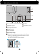
Name and function of the Parts 9 2 AUDIO OUT Rear View 1 8 COMPONENT AC-IN DC-OUT HDMI/DVI Y PB PR D-SUB 7 6 1 3 2 4 5 1 AC-IN Connector : Connect the Power Cord 2 DC-OUT Jack 3 HDMI/DVI Signal Connector 4 COMPONENT Input Terminal 5 D-SUB Analogue Signal Connector 6 Kensington Security Slot 7 USB UP stream Port(1EA) 8 USB DOWN stream Port(2EA) 9 Audio out Jack(Headset/Earphone/connecting terminal of the Speaker) : You can use the AUDIO-OUT Jack by connecting earphones or a headset w
Connecting to External Devices When Connecting to your PC 1. Place the monitor in a convenient, well-ventilated location near your computer. To adjust height of your monitor, unlock the stand lock on top of the stand. 2. Connect the signal cable. When attached, tighten the thumbscrews to secure the connection. 1 3. Connect the power cord into a proper power outlet that is easily accessible and close to the display. 2 1 2 AUDIO OUT Varies according to model.
Connecting to External Devices When Watching DVD/Video/HDTV When connecting with a Component cable 1. Connect the Component cables and RCA to Stereo cables properly. Connect the terminals to the sockets of the same color. 2. Connect the power cord. 1 2 AUDIO OUT PB PB COMPONENT DC-OUT HDMI/DVI Y PB PR D-SUB PR PR Monitor Speaker AUDIO IN RCA-Stereo cable (not included) Component Cable (not included) DVD/VIDEO/HDTV PB PB PR PR DVD/VIDEO/HDTV 3.
Connecting to External Devices When Watching DVD/Video/HDTV When connecting with a HDMI/DVI cable 1 2 AUDIO OUT 1. Connect the HDMI/DVI cables and RCA to Stereo cables properly. COMPONENT DC-OUT HDMI/DVI Y PB PR D-SUB Speaker (not included) RCA-Stereo cable HDMI/DVI cable (not included) DVD/VIDEO/HDTV 2. Press the INPUT button at the front side of the monitor. INPUT OK/AUTO INPUT RGB HDMI Component When connecting with a HDMI/DVI cable. • Select HDMI.
Connecting to External Devices Connecting the USB(Universal Serial Bus) Cable "USB (Universal Serial Bus)" is an innovation in connecting your different desktop peripherals conveniently to your computer. By using the USB, you will be able to connect your mouse, keyboard, and other peripherals to your display instead of having to connect them to your computer. This will give you greater flexibility in setting up your system.
Connecting to External Devices To arrange the cables After connecting the cables neatly, arrange the cables to the Cable Holder as shown in the following figure. 1 2 AUDIO OUT 1. AUDIO-OUT To connect HDMI, make sure that the audio cables are plugged in as show in the diagram. COMPONENT DC-OUT HDMI/DVI Y PB PR D-SUB Cable Holder *The length of the cable which connects the monitor’s AUDIO-OUT and the speaker’s AUDIO-IN can be too long.
Control Panel Functions Front Panel Controls INPUT Button Select the input signal. INPUT OK/AUTO : 15-pin D-SUB analogue signal : HDMI/DVI digital signal DTV SET-TOP BOX,Video,DVD Component : DTV SET-TOP BOX,Video,DVD RGB HDMI MENU Button Controls locked Controls unlocked INPUT RGB HDMI Component Use this button to enter or exit the On Screen Display. Controls locked/Controls unlocked This function allows you to lock the current control settings, so that they cannot be inadvertently changed.
Control Panel Functions Use this button to select an icon or adjust the setting in the OSD screen. Button Button • Use this button to directly control brightness and contrast of the PC signal (RGB, HDMI/DVI). Sub screen Button • (Picture In Picture) Button The sub-screen is switched on and off by pressing the button. OK/AUTO Button Auto in progress For optimal display change resolution to 1920x1200 Main screen Use this button to enter a selection in the On Screen Display.
On Screen Display (OSD) Control Adjustment Screen Adjustment Making adjustments to the image size, position and operating parameters of the display is quick and easy with the On Screen Display Control system. A short example is given below to familiarize you with the use of the controls. The following section is an outline of the available adjustments and selections you can make using the OSD. NOTE Allow the display to stabilize for at least 30 minutes before making image adjustments.
On Screen Display(OSD) Selection and Adjustment OSD (On Screen Display) menu Icon Function Description Adjusting Screen Colour. PICTURE Selecting the options. SPECIAL Screen Adjustment. SCREEN Adjusting PIP Mode (Multiple Screen) Functions. PIP NOTE OSD(On Screen Display) The OSD function enables you to adjust the screen status conveniently since it provides graphical presentation.
On Screen Display(OSD) Selection and Adjustment Adjusting Screen Colour EZ Video HDMI(Video), Component input The EZ Video function automatically adjusts the screen image quality depending on the AV usage environment. • Dynamic : Select this option to display with a sharp image. • Standard : The most general and natural screen display status. • Mild : Select this option to display with a mild image. • Game : Select this option to enjoy dynamic image when playing a game.
On Screen Display(OSD) Selection and Adjustment Adjusting Screen Colour PC only CSM EZ Video • 6500K/9300K/sRGB Selecting a factory setting colour set. 6500K: Slightly reddish white. 9300K: Slightly bluish white. sRGB : Set the screen color to fit the SRGB standard color • User : Select this option to use the user-defined settings. CSM User Contrast To adjust the contrast of the screen. Brightness To adjust the brightness of the screen. Red / Green / Blue Set your own colour levels.
On Screen Display(OSD) Selection and Adjustment Selecting the options Input Child lock Language Power indicator Transparency Reset DDC-CI Input If you press the button once, the following Input Signal Window will appear. Select the signal type you want using the button. Input Child lock Language Power indicator Transparency Reset DDC-CI Child lock This feature can prevent unauthorized viewing. In order to lock the OSD screen adjustment, set the Child lock tab to the 'On' position.
On Screen Display(OSD) Selection and Adjustment Screen Adjustment ARC To select the image size of the screen. Full Original Full Original 1:1 Autoconfigure This function is suitable for analogue signal input only. This button is for the automatic adjustment of the screen Position, Clock and Phase. Clock This function is suitable for analogue signal input only. To minimize any vertical bars or stripes visible on the screen background.
On Screen Display(OSD) Selection and Adjustment Screen Adjustment HDMI Video: Used when it is connected with DVD or SET-TOP BOX through HDMI. * If you want to connect VCR, select VIDEO in this menu. Otherwise, you may see noise in the margin of the screen due to the difference in the screen size . PC : Used when it is connected with PC through HDMI. * If you want to connect PC, select PC in this menu.
On Screen Display(OSD) Selection and Adjustment Adjusting PIP Mode (Multiple Screen) Functions (To adjust the sub screen) On/Off Off PIP Input PIP Position On/Off PIP Input PIP After selecting PIP in the PIP On/Off menu, the following menu items can be adjusted. To select an input signal for PIP. To adjust the position of PIP screen.
Troubleshooting Check the following before calling for service. No image appears ● Is the power cord of the • Check and see if the power cord is connected properly to the power outlet. display connected? ● Is the power on and the • Adjust the brightness and the contrast. power indicator blue or green? ● Is the power indicator amber? • If the display is in power saving mode, move the mouse or press any key on the keyboard to activate the screen. • Turn on the PC.
Troubleshooting Display image is incorrect ● Display Position is incorrect. • Press the OK/AUTO button to automatically adjust your display image to the ideal setting. If the results are unsatisfactory, adjust the image position using the H position and V position icon in the on screen display. ● On the screen background, vertical bars or stripes are visible. • Press the OK/AUTO button to automatically adjust your display image to the ideal setting.
Troubleshooting Display image is incorrect ● The screen color is mono or abnormal. • Check if the signal cable is properly connected and use a screwdriver to fasten if necessary. • Make sure the video card is properly inserted in the slot. • Set the color setting higher than 24 bits (true color) at Control Panel - Settings. ● The screen blinks. • Check if the screen is set to interlace mode and if yes, change it to the recommend resolution.
Specifications Display Sync Input Video Input Resolution 24 inches (61.3 cm) Flat Panel Active matrix-TFT LCD Anti-glare coating 24 inches viewable 0.270 mm pixel pitch Horizontal Freq. Analog : 30 - 83 kHz (Automatic) Digital : 30 - 83 kHz (Automatic) Vertical Freq. 56 - 75 Hz (Automatic) Input Form Separate TTL, Positive/Negative Composite TTL, Positive/Negative SOG (Sync On Green), Digital(HDCP) Signal Input 15 pin D-Sub Connector HDMI/DVI connector(Digital), Component Input Form RGB Analog (0.
Specifications Stand Base Attached ( Power cord Wall-outlet type or PC-outlet type USB Standard USB 2.0, Self-Power Data Rate Max 480 Mbps ), Detached ( O ) Power Consumption Max 2.5W x 2 NOTE Information in this document is subject to change without notice.
Specifications PC INPUT Preset Modes (Resolution) Display Modes (Resolution) 1 2 3 4 5 6 7 8 9 10 640 x 480 640 x 480 720 x 480 720 x 400 800 x 600 800 x 600 1024 x 768 1024 x 768 1152 x 864 1280 x 768 Horizontal Vertical Freq. (kHz) Freq. (Hz) 31.469 37.500 35.162 31.500 37.879 46.875 48.363 60.023 67.500 47.776 59.940 75.000 59.901 70.156 60.317 75.000 60.004 75.029 75.000 59.
Specifications HDMI Type Pin Assignment No.19 No.1 No.2 No.18 Type A pin 1 2 3 4 5 6 7 8 9 10 11 12 13 14 15 16 17 18 19 Signal Name T. M. D. S. Data2+ T. M. D. S. Data2 Shield T. M. D. S. Data2T. M. D. S. Data1+ T. M. D. S. Data1 Shield T. M. D. S. Data1T. M. D. S. Data0+ T. M. D. S. Data0 Shield T. M. D. S. Data0T. M. D. S. Clock+ T. M. D. S. Clock Shield T. M. D. S. ClockCEC Reserved(In cable but N.C.
Installing the Wall mount plate This monitor satisfies the specifications of the Wall mount plate or the interchange device. After moving the product to face downward, make sure to place it on a soft cloth or a cushion to avoid surface damage. 1 2 AUDIO OUT 1. COMPONENT HDMI/DVI Y PB PR D-SUB 2. Separate the head and the stand with the use of a screwdriver. 3. Install the Wall mount plate.
Digitally yours