Installation manual PV Solar MODULE Please read this manual carefully before operating your set and retain it for future reference. N-TYPE MODELS LGXXXN1C(W,K)-G4 LGXXXN2C(W)-G4 MFL69534401 (Rev 01) P-TYPE MODELS LGXXXS1C(W)-G4 LGXXXS2C(W)-G4 www.lgsolarusa.
TabLE Of CONTENTS SafETY ..................................................................03 bEfOrE & afTEr INSTaLLaTION ......................05 Before Installation ................................................................................05 After Installation ...................................................................................05 ELECTrICaL INSTaLLaTION ...............................06 Danger ..........................................................................................
SafETY The instructions related to safety and use indicated in the this installation manual are intended for the prevention of unexpected danger, damage, or failure. DaNgEr WarNINg CaUTION Non-compliance with the instructions may cause product damage, product failure, and/or serious bodily injury or death. DaNgEr Do not contact electrically active parts of the panel, such as terminals, without appropriate safety gear. Contact may result in lethal spark or electric shock.
Do not touch the glass surface or frame of the solar module after installation of the module. It may result in injury or death. Heavy objects must be kept off of the solar module. Do not stand on or step on the module. Do not drop the module. Failure to comply may result in product damage, product failure or bodily injury. Do not scratch the coating surface of the frame. Scratches may decrease the total solar output due to corrosion of the frame.
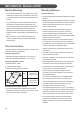
bEfOrE & afTEr INSTaLLaTION before Installation after Installation Please carefully read this manual before installation. • Plug in the connector tightly and ensure that the wiring properly works. • Solar module installation and maintenance must be performed by qualified and authorized installer. • All installation instructions should be read and understood before performing any installation. • Do not disassemble the solar module.
ELECTrICaL INSTaLLaTION Danger Diodes • Avoid all electrical hazards when installing, wiring, operating and maintaining all panels. • All LG modules are equipped with factory installed bypass diodes. The factory-installed diodes provide proper circuit protection for the systems within the specified system voltage. • Do not connect panels that have different electrical properties or physical configurations in the same system.
Parallel Connection Earth grounding • The solar modules may be combined in parallel to produce the desired current output. • All work must be conducted in conformance with all Federal, State, and local codes and standards. • Grounding works should be performed by an authorized installer for the safety and maintenance of the system in accordance with all national, state and local electrical codes and regulations and standards.
MEChaNICaL INSTaLLaTION Module Mounting Mounting Methods • The LG Electronics’ (LGE) Limited Warranty for solar modules is contingent upon modules being mounted in accordance with the requirements described in this section.
• When installing modules in heavy snow areas, it is recommended to be taken an appropriate countermeasure to prevent possible damages to the lower side frame by slipping snow. We recommend to use corrosion resistant material according to standard UL 1703 or UL2703 for these supporting part. (A snow guard should be installed in accordance with the manufacturer’s instructions.
DISCLaIMEr Of LIabILITY / DISPOSaL Disclaimer of Liability • By beginning to installation process, the installer has to read and completely understand this Installation Manual. • If installer had any questions regarding this installation manual, the installer would have contacted LG with any questions or concerns.
PrODUCT SPECIfICaTIONS N-TYPE Electrical and Mechanical Properties(Rated electrical characteristics are -5 to +5 percent) Standard Test Condition(STC) : Irradiation 1000W/m2, Cell temp. 25℃, 1.5AM Electrical Properties LGXXXN2C(W)-G4 LGXXXN1K-G4 LGXXXN1C(W)-G4 Module Series Model Name Pmax Power Voc at at STC Tolerance STC Isc at STC Mechanical Properties Max. Max.
P-TYPE Electrical and Mechanical Properties(Rated electrical characteristics are -5 to +5 percent) Standard Test Condition(STC) : Irradiation 1000W/m2, Cell temp. 25℃, 1.5AM Electrical Properties LGXXXS2C(W)-G4 LGXXXS1C(W)-G4 Module Series Model Name Power Voc at Pmax at STC Tolerance STC Isc at STC Mechanical Properties Max. Max. Vmpp Impp at Series System Connector Length Fuse at STC STC Voltage Rating Height Weight W % V A V A A V mm mm mm kg LG250S1C(W)-G4 250 3% 37.9 8.
Dimensions of Modules Unit: mm / in. 60Cell Module 72Cell Module 1000.0/39.37 (Size of Short Side) 1000.0/39.37 (Size of Short Side) 4-5.5*4.0/0.22*0.16 Drain Holes 4-7.5*4.0/0.30*0.16 Drain Holes 4-5.5*4.0/0.22*0.16 Drain Holes 960.0/37.80 (Distance between Mounting & Grounding Holes) 150.0/5.91 960.0/37.80 (Distance between Mounting & Grounding Holes) 4-7.5*7.0/0.30*0.28 Drain Holes 1000.0/39.37 Cable Length 4-Ø4.3/0.17 Grounding Holes 1960.0/77.17 (Size of Long Side) 1420.0/55.
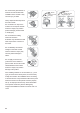
aPPENDIx Mechanical Installation : 60Cell Model fig.1 Mounting Type fig.2 Clamping Type ① ② A B ① ② ② ① ② ① ① : 170mm(6.7 in) ② : 270mm(10.6 in) B A Front : 6000Pa(125psf) Rear : 5400Pa(113psf) A : 150mm(5.9 in) B : 400mm(15.7 in) fig.3 Clamping Type Front : 6000Pa(125psf) Rear : 5400Pa(113psf) fig.4 Clamping Type A A B B B B A A A : 150mm(5.9 in) B : 400mm(15.7 in) Front : 6000Pa(125psf) Rear : 5400Pa(113psf) A : 120mm(4.7 in) Front : 1800Pa(37.5psf) Rear : 1800Pa(37.5psf) B : 150mm(5.
Mechanical Installation : 72Cell Model fig.1 Mounting Type fig.2 Clamping Type ① ② A B ① ② ② ① ② ① ① : 270mm(10.6 in) ② : 370mm(14.6 in) B A Front : 5400Pa(113psf) Rear : 4300Pa(90psf) A : 250mm(9.8 in) B : 400mm(15.7 in) fig.3 Clamping Type Front : 5400Pa(113psf) Rear : 4300Pa(90psf) fig.4 Clamping Type A A B B B B A A A : 250mm(9.8 in) B : 400mm(15.7 in) Front : 5400Pa(113psf) Rear : 4300Pa(90psf) A : 120mm(4.7 in) Front : 1800Pa(37.5psf) Rear : 1800Pa(37.5psf) B : 250mm(9.
fig7. Mounting Type ① ① ① ① ① : 780mm(30.
alternate Equipment grounding Devices This appendix defines alternative grounding methods for LG PV modules and applies to the LG Module Install manual and listed manufacture’s installation guide. These alternative grounding devices indicated on this page has been evaluated and approved by LG, not by ETL. If such devices want to be used to meet the requirement in UL 1703, some adequate tests shall be conducted in accordance with UL1703 additionally.
LG Electronics U.S.A Inc. 1000 Sylvan Ave, Englewood Cliffs, NJ 07632 Contact : lg.solar@lge.com http://www.lgsolarusa.com This document is subject to change without notice. LG, LG logo and Life's Good are trademarks of LG Electronics, Inc. worldwide. Trademarks and intellectual properties of LG Electronics, Inc. are protected by international copyright laws.