
Owner's Manual


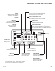
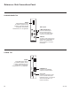
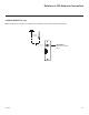
Table Of Contents
- COVER
- WARNING / CAUTION
- SAFETY INSTRUCTIONS
- CONTENTS
- FEATURES OF THIS TV
- PREPERATION
- ACCESSORIES
- FRONT PANEL INFORMATION
- BACK PANEL INFORMATION
- STAND INSTRUCTIONS
- CABLE MANAGEMENT
- DESKTOP PEDESTAL INSTALLATION
- SWIVEL STAND
- ATTACHING THE TV TO A DESK
- VESA WALL MOUNTING
- SECURING THE TV TO THE WALL TO PREVENT FALLING WHEN THE TV IS USED ON A STAND
- ANTENNA OR CABLE CONNECTION
- MPI CARD SLOT / PPV CARD INSTALLATION
- EXTERNAL EQUIPMENT SETUP
- WATCHING TV / CHANNEL CONTROL
- USB
- PICTURE CONTROL
- SOUND & LANGUAGE CONTROL
- TIME SETTING
- PARENTAL CONTROL / RATINGS
- APPENDIX
- COMMERCIAL MODE SETUP GUIDE
- Safety Warnings
- IMPORTANT SAFETY INSTRUCTIONS
- Table of Contents
- Commercial Mode Overview
- Pro:Centric Operation
- Installer Remote Control Typical Key Functions
- Master TV Setup
- Installer Menu
- Channel Icons / Custom Text Labels (2-5-4 + MENU Mode)
- Cloning Overview
- USB Cloning Procedures
- Clone Programmer Cloning Procedures
- FTG Mode of Operation Overview
- FTG Mode via CPU
- FTG Mode via EBL (Local Configuration)
- FTG File Manager Utilities Overview
- IP Environment Setup
- Remote Jack Pack / TV Connections & Setup
- Reference
- Upgrading TV/PTC Software using a USB Memory Device
- Downloading a Splash Screen Image
- Power Consumption Settings
- TV Camport Auto Sense Operation
- TV Aux Input Configuration
- b-LAN Setup & Overview
- RJP Model List and Input Auto-sensing Hierarchy
- Resetting Factory Defaults on the TV(s)
- TV Zone Restrictions
- LD660H/LD665H Rear Jack Panel
- LV555H Rear Jack Panel
- Side Connections Panel
- RF Antenna Connection
- Troubleshooting
- Glossary of Terms
- Document Revision History / Notes
- BACK COVER

54
206-4200
A b-LAN enabled head end device, such as an LG FMA-LG101, broadcasts over the RF distribution system to
communicate to multiple TVs. When the TV is first installed, it must be turned ON in order for its embedded
b-LAN module to receive communication from the head end device. At this point, if it is desired for the b-LAN
module to always be powered, including while the TV is in Standby, set Installer Menu item 118 POWER
SAVINGS to 001.
Also, if MPI communication is required for external MPI control, set Installer Menu item 118 POWER SAVINGS
to 001 so that the GAME CONTROL/MPI port circuitry is always powered.
Reference: b-LAN Setup & Overview
POWER
SAVINGS
001 On On
003 (default) Off On
The b-LAN module is internal to the TV. It allows hotel/institution head end equipment with b-LAN technology
to communicate, via the institution’s RF distribution system, with the TV for configuration and control.
Note: MPI cards with b-LAN technology—LMT7Z5, LMT7Z7, LMT7Z9—are NOT supported in TVs in which
b-LAN technology is already integrated.
Installer Menu item 118 POWER SAVINGS controls the power circuitry for both the embedded b-LAN module
and the GAME CONTROL/MPI port. The default value is 003—the b-LAN module as well as the GAME
CONTROL/MPI port circuitry is only powered when the TV is turned ON. See chart below.
TV Power On State
TV Standby State
b-LAN & GAME
CONTROL/MPI Port
Power
b-LAN & GAME
CONTROL/MPI Port
Power