ENG ENGLISH Easy Setup Guide LG Digital Signage (MONITOR SIGNAGE) Please read this manual carefully before operating your set and retain it for future reference. 47LV35A 55LV35A *MFL68621511* P/NO : MFL68621511(1806-REV02) Printed in Korea www.lg.
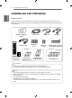
ASSEMBLING AND PREPARING ENGLISH ENG ASSEMBLING AND PREPARING Accessories Check your product box for the following items. If there are any missing accessories, contact the local dealer where you purchased your product. The illustrations in this manual may differ from the actual product and accessories.
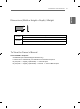
ASSEMBLING AND PREPARING H W 47LV35A 55LV35A D 1044.9 mm x 590.0 mm x 89.9 mm / 16.5 Kg 43.1 inches x 23.2 inches x 3.5 inches / 36.3 lbs 1213.4 mm x 684.2 mm x 88.5 mm / 23 Kg 47.7 inches x 26.9 inches x 3.4inches / 50.7 lbs To View the Owner’s Manual Insert CD-ROM in Computer. CD-ROM will open automatically.(for Windows only) If it does not run automatically, it is available to see the below sequence. My computer ➙ Digital_LG(CD-ROM) ➙ Index.
SAFETY PRECAUTIONS PRECAUTION IN MOVEMENT ENGLISH ENG Adhere to the warning signs printed on the Box. Don’t tumble the Set box sideward down. Do not Clamp Do not drop from clamping. 2 Persons needed for transport Load with care. Do not drop from stacking. 4 Persons needed for transport Do not transport horizontally. Do not drop from carrying. This way up/ Fragile/ Keep away from rain/ Stacking limit 4. Don't lie on or lean on the Set box.
SAFETY PRECAUTIONS Precaution Move the Set as a team of 2 persons. When you move the bare Set, please use one hand on grabbing the handle and the other support under the Set. 1 Be careful not to collide the sets with the floor or with each other. Install in the space with enough airflow.
SAFETY PRECAUTIONS ENGLISH ENG Causes & Phenomena of the Line Defect COF (CHIP ON FILM) DEFECT The line defect would occur on your Set if you strike on the edge of the Set.
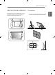
INSTALLING THE PRODUCT 7 Installing the Product Cut Packing Strap of the Box. 2 Cut Tape on the Box. 3 Open the Box and remove the top packing. 4 Remove the Upper Box. 5 Open the Poly Bag. 6 Undress the Poly Bag.
INSTALLING THE PRODUCT 7 Lift up the Set using the SIDE/BACK Handle. 8 9 With one hand under the set and the other hand grabbing the set, move the set. Remove Bottom packing when lifting up the Set. ENGLISH ENG 10 Lay the back of the Set down on the table.
INSTALLING THE PRODUCT 9 11 Use the cushion or Pad when you lay the face of the Set downward. ENG ENGLISH 12 Connect IR receiver to use remocon. And then, connect power cord .
TILING DISPLAYS Tiling Displays ENGLISH ENG How to Mount the Set Example of 2 x 2 tiling 55LV35A 47LV35A Screws for attaching the VESA wall mount 16-M4 Screw ≤ 6 mm Screws for attaching the VESA wall mount 16-M4 Screw ≤ 6 mm CAUTION When you connect Monitor sets for multivision, you may find that the screen color is not the same yy across all the Monitor sets. If you want to adjust the screen color manually, please refer to the Installation Manual.
TILING DISPLAYS 11 How to Join Sets 1 Join other sets using screws for fixing the VESA wall mount in the same way as above. Set 4 joined to the rest of the sets (2 x 2 tiling) 2 After joining the sets, use the tiling guide to adjust the gap between the sets. 3 Now the 2 x 2 tiling is complete. You can tile in various combinations, such as 3 x 3. 55LV35A 1 Join other sets using screws for fixing the VESA wall mount in the same way as above.
REMOTE CONTROL ENGLISH ENG REMOTE CONTROL The descriptions in this manual are based on the buttons of the remote control. Please read this manual carefully and use the Monitor set correctly. To replace batteries, open the battery cover, replace batteries (1.5 V AAA) matching and ends to the label inside the compartment, and close the battery cover. To remove the batteries, perform the installation actions in reverse. CAUTION Do not mix old and new batteries, as this yy may damage the remote control.
REMOTE CONTROL 13 ENG ENGLISH INFO Displays information about the program or screen that is currently used. SETTINGS Accesses the main menus or saves your input and exit menus. OK Selects menus or options and confirms your input. BACK Allows the user to move back one step in user interaction function. Allows you to control various multimedia devices simply by using the remote control through the SimpLink menu. (It may not be supported depending on the model.).
MAKING CONNECTIONS < Connecting to a PC> ENGLISH ENG OUT USB IN DVI IN DVI OUT RGB/ AV /COMPONENT IN HDMI IN IR IN LAN DVI OUT 15-pin D-Sub Signal Cable (Max 3 m) DVI OUT RGB OUT CAUTION Connect the signal input cable and tighten it by turning the screws yy clockwise.
MAKING CONNECTIONS < External Device Connection> ENG ENGLISH Camcorder/Camera/ HD Receiver/DVD Direct Connection/Using the Router/Using the Internet DVI OUT USB Network IN OUT USB IN DVI IN DVI OUT RGB/ AV /COMPONENT IN IR IN 15-pin D-Sub Signal Cable (Max 3 m) HDMI HD Receiver/DVD/ Gaming Device/ Camcorder/Camera HD Receiver/DVD/VCR Gaming Device/ Camcorder/Camera CAUTION Connect the signal input cable and tighten it by turning the screws yy clockwise.
MAKING CONNECTIONS Connecting the Power code ENGLISH ENG 55LV35A 47LV35A 2 2 1 Power Button NOTE Select an input signal.
RGB /COMPONENT OUT RGB /COMPONENT OUT RGB /COMPONENT OUT RGB /COMPONENT OUT RGB /COMPONENT IN RGB /COMPONENT IN RGB /COMPONENT IN RGB /COMPONENT IN MAKING CONNECTIONS 17 Daisy Chain Monitors ENG ENGLISH DVI Cable DVI IN DVI OUT DVI IN DVI OUT DVI IN DVI OUT DVI IN DVI Cable (Max 3m) Monitor Set 1 Monitor Set 2 Monitor Set 3 Monitor Set 4 NOTE For DVI, in general, up to 12 monitors can be connected via the DVI Out port (at the recommended yy resolution) if the signal is stable and ther
INSTALLATION MULTIVISION CONFIGURATION ENGLISH ENG Function Setting 1 IR Receiver connection. 2 Connecting the Power code. 3 Set ID setup for each set. 4 IR Receiver removal for all sets except for Set 1. 5 RGB connection. 6 Connect the Monitor sets, in series, using an RS-232C cable. RS-232C Cable PC Monitor Set 1 Monitor Set 2 Monitor Set 3 7 Installation Menu setup. Installation Menu (V 3.
INSTALLATION 19 White Balance Adjust Menu • R-Gain ◄ 187 • G-Gain 184 • B-Gain 184 • Backlight ► 80 • Reset To Set Close R-Gain Adjusts the level of red. The higher the number, the redder the set. Decrease the number if the screen looks too red. G-Gain Adjusts the level of green. The higher the number, the greener the set. Decrease the number if the screen looks too green. B-Gain Adjusts the level of blue. The higher the number, the bluer the set.
INSTALLATION Setting the Tile Mode ENGLISH ENG In Tile Mode you can view an image in a larger scale by connecting multiple monitors. 1x2 When using 2 monitors ID 1 Tile Mode Off: An input image is not yy enlarged, and the same image is shown on all connected monitors. Tile Mode On: An input image is enlarged yy according to the value in the H. Set Count and V. Set Count fields.
INSTALLATION 21 Setting the Picture ID The IR signal of the remote control is yy transmitted through the RS232C cables connected in serial mode. When you set a Picture ID using the remote yy control, you can only control the Set that matches the Picture ID. ex) For example, if you set a Picture ID to 2, you can only control the monitor with the Set ID 2. If Picture ID is set to Off, you can control all monitors at the same time. 1 Press the red ON button Von the remote control to assign the Picture ID.