INSTALLATION MANUAL LED TV Please read this manual carefully before operating your set and retain it for future reference.
TABLE OF CONTENTS 3 Digital Signage Media Player 3 Digital Signage Media Player Overview 4 Installation menu 2 4 5 13 13 19 21 22 23 25 26 27 29 31 32 33 34 Introduction Public Display Mode TV Manager - 1. USB - 2.
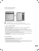
Digital Signage Media Player Digital Signage Media Player Overview (* Only for LX540S, LX530S series) The Digital Signage Media Player can play content produced and distributed by SuperSign Elite-W. Supported content types consist of photographs, videos, external inputs such as TV broadcasts, texts, and music. (1 ) Executable content yy*.cts : These files can be played at any time. yy*.sce : These files can be played at any time like *.cts files or they can be played to a specific schedule.
Installation Menu Introduction he abundant functions for Hotel TV linked with software installation can be projected on OSD as T ‘Installation Menu’. The wide range of hotel features can be performed simply on additional window to enhance the LG hotel TV’s easy installation and convenient operation for Hotelier and System Integrators. Image shown may differ from your TV. yy Installation Menu (V 3.
Public Display Mode Image shown may differ from your TV. yy Public Display Settings (V 3.0) Installation Menu (V 3.0) ▲ LG Hotel Mode Setup Public Display Settings TV Manager Password Change Set ID Setup Configuration Setup Multi Timer Lock Mode External Speaker HCEC Setup S/W : 02.00.00.01 Micom : 0.00.
(3) Volume (0 ≤ Min ≤ Start ≤ Max ≤ 100) Decide to apply volume policy of ‘Start Volume’, ‘Maximum Volume’ and ‘Minimum Volume’ yy as Yes(Work) or No(Do Not Work). (3-1) Start Volume This entry sets the start volume level when is power on. The level is specified as a number between minimum volume to maximum value. (Min ≤ Start ≤ Max) yy The default setting is ‘Off’ (disabled).
(4-2) Local Key Operation Decide to operate 'Local/Front Key' working behavior by setting ‘Local Key Operation’ as Normal, Use PWR Only, Block All. (LX300C series use for only Normal/Block All) When 'Local Key Operation' is set to Block All, all local keys don’t work. If value is Use PWR Only, it yy blocks all local keys except power key. When 'Local Key Operation' is set to Normal, all local key are available.
(5-3) Channel Change Decide to change channel or not by setting ‘Channel Change' as ‘Yes’(Change Possible) or ‘No’(Change Impossible) when present source is TV. When ‘Channel Change' is set to No (Change Impossible) yy »»Channel Key, Numeral Key, List Key, Q.View Key don't work and entering 'Channel Menu' in the Main Menu OSD is impossible. »»‘Channel' item in 'On Time' menu will be fixed. »»Entering ‘Setup Menu' in the 'Main Menu’ OSD is impossible regardless of ‘Setup Menu' item.
(6) Power Management The Power Management feature will turn off the television receiver if no input control command is received from either the Local or IR Key within a selected hours. Activity on either of these inputs shall restart the ‘Power Management’ timer and check key time interval yy again. This entry can be set to a value which is corresponding to the desired hours (1 to 7). yy Default value is ‘Off(disabled)’. yy TV should off and on after apply this setting.
(8-2) Tune Mode Tune the selected start channel with physical or virtual method. Usually, digital channel uses virtual channel and analog channel uses physical channel. (8-3) Major Select major part of start channel number if Input source value is TV. (in case of ATV, it means physical channel number.) (8-4) Minor Select minor part of start channel number if Input source value is TV.
(10) Factory Reset Factory reset returns all the parameters to the default settings. • Factory Reset Confirm Press ‘Enter key’ to proceed factory reset. and confirmation message window will be shown. yy All user settings and channel settings will be reset. Still Continue? Yes No When select ‘Yes’, all television settings except UTT value should write to the default settings.
Public Display Settings (Value Range Table) Item Public Display Mode Power On Status Volume Start Volume Enable Disable Yes No No - - *STD Yes No No Off, Minimum Volume ~ Maximum Volume Off Maximum Volume Minimum Volume ~ 100 100 Minimum Volume 0 ~ Maximum Volume Key Management Yes 0 No No IR Operation Work (0) / Use PWR Only (1) / Bock All (2) Work (0) Local Key Operation Work (0) / Use PWR Only (1) / Bock All (2) Work (0) Limited Mode Yes No No Setup Menu Yes No Yes In
TV Manager 1. USB Ez Download Ez Download is a function that enables users to download the desired items all at once, such as EPK(software update file), TLL (see Send to USB descriptions for more information regarding file types), LogoImage, NoSignal Image, Welcome Video, etc (TLX, MICOM for Pro:Centric). * Splash images and EPK files and Welcome Video files should be copied into the folder named LG_DTV on the USB. TLL file should be copied to the root folder of the USB.
5 Select the EPK option (software update) and then use the green and yellow buttons to download either SPI Boot or LG Boot Logo. If you checked the LG Boot Logo checkbox, then the Splash image, if selected, will be unchecked. Also, if you select the LG Boot Logo and proceed with the download, the existing Splash image will be deleted. Ez Download (USB Port1) [TLL] GlobalClone00001.TLL [LOGO] 1024 X 768.jpg [EPK] M1A_DVB_CN_RevNo1539_v00.00... [NOSIG] 1360X 768.jpg [NOSIG] Nosignallmage.
USB Cloning An Installer can quickly set up and clone multiple TV sets at a property. These cloned TVs will all have the same Master TV Setup: Public Display Mode Installation Menu settings, User A/V settings and the Channel Map. This newer procedure significantly decreases the installation time that would be necessary if the standard RS-232C method were used instead.
Receive From USB Image shown may differ from your TV. yy 1 Plug USB memory card into the USB port of the TV. 2 Use the button to select the TV Manager option and then press the OK button. Installation Menu (V 3.0) Public Display Settings TV Manager Password Change Set ID Setup Configuration Setup Multi Timer Lock Mode External Speaker HCEC Setup S/W : 02.00.00.01 Micom : 0.00.84 3 OK Use the button to select the USB and Receive from USB and press the OK button.
Send To USB Image shown may differ from your TV. yy 1 Plug USB memory card into the USB port of the TV. 2 Use the button to select the TV Manager option and then press the OK button. Installation Menu (V 3.0) Public Display Settings TV Manager Password Change Set ID Setup Configuration Setup Multi Timer Lock Mode External Speaker HCEC Setup S/W : 02.00.00.01 Micom : 0.00.84 3 OK button to select the USB and Send to USB and press the OK button.
Logo Image Download 1 2 1 AV (RGB) IN 3 AUDIO IN COMPONENT OPTICAL (COMPONENT/RGB/DVI) AUDIO OUT IN Connect the USB device to the USB IN jack on the TV. USB IN /DVI IN PCMCIA CARD SLOT Make a ‘LG_DTV’ folder on the USB flash drive and then copy the splash image file to that folder. Image shown may differ from your TV. yy RGB IN (PC) 2 RS-232C IN (CONTROL & SERVICE) ANTENNA/ CABLE IN button Use the to select the TV Manager option and then press the OK button. Installation Menu (V 3.
2. Diagnostics Diagnostics Setup Introduction This diagnostic function provides current status information of the TV in XML file format using a USB device. If the user sets a signal standard level, SignalTrace checks the signal strength status of the digital channel that the user tuned to. It checks and records good and bad channel signals, and then provides the signal information to a USB storage device in XML file format. Installation Menu (V 3.
(3) Saving signal status information of digital channels through SignalTrace in XML format Go to Installation menu -> TV Manager -> Diagnostics -> Diagnostics Setup yy Set the level value in Signal Tracer Set. (Disable, 10 to 90) yy TV Manager USB Diagnostics Setup Diagnostics Setup Signal Tracer Set Diagnostics Previous Previous ◄ Disable ► OK OK Change the channel and tune to a digital channel, then maintain the status for more than 5 yy seconds. Create an empty file named tv_signal.
Password Change Image shown may differ from your TV. yy - To ensure more security, Password can be changed by installers’ own design. Installation Menu (V 3.0) Public Display Settings TV Manager Password PasswordChange Change Set ID Setup Configuration Setup Multi Timer Lock Mode External Speaker HCEC Setup S/W : 02.00.00.01 Micom : 0.00.84 Password Change Change Password * * * * Confirm Password * * * * Previous OK OK 1 Use the 2 Enter four digit password.
Set ID Setup Installation Menu (V 3.0) Public Display Settings TV Manager Password Change Set Set ID ID Setup setup Configuration Setup Multi Timer Lock Mode External Speaker HCEC Setup S/W : 02.00.00.01 Micom : 0.00.84 1 Use the Set ID Setup Set ID Lock Set ID Previous ◄ Yes ► 1 OKOK OK button to select the Set ID Setup. •S et ID Lock - Set the ‘Set ID’ item in ‘Option’ Menu whether to activate or not. - Set to Yes(Work) or No(Do Not Work). •S et ID - Set the ‘Set ID’ of TV Set with 1~99.
Configuration Setup Image shown may differ from your TV. yy Installation Menu (V 3.0) Configuration Setup Public Display Settings TV Manager Password Change Set ID Setup Configuration ConfigurationSetup Setup Multi Timer Lock Mode External Speaker HCEC Setup S/W : 02.00.00.01 Micom : 0.00.
(4) 15Min Auto Off When ‘15Min Auto Off’ is set to ‘Enable’, TV will turn off if there is no signal in 15Min. yy (5) Auto Sensing -If 'Auto Sensing' is set to 'To Set ⊙', the input is automatically switched when the input signal that yy you set to 'ON' is received. If 'Auto Sensing' is set to 'Disable', the input is not switched when the input signal is received. yy If SIMPLINK is set to On, HDMI is automatically set to Disable and can not work.
Multi Timer Installation Menu (V 3.0) Public Display Settings TV Manager Password Change Set ID Setup Configuration Setup Multi MultiTimer Timer Lock Mode External Speaker HCEC Setup S/W : 02.00.00.01 Micom : 0.00.84 1 Use the Multi Timer Multi Timer ◄ On ► On Timer Off Timer Previous OK OK button to select the Multi Timer. (1) Multi Timer It is a mode to set whether to use or not. yy When ‘Multi Timer’ is set to ‘On’, You can adjust ‘On Timer’, ‘Off Timer’ menu.
Lock Mode Installation Menu (V 3.0) Public Display Settings TV Manager Password Change Set ID Setup Configuration Setup Multi Timer Lock LockMode Mode External Speaker HCEC Setup S/W : 02.00.00.01 Micom : 0.00.84 1 Use the Lock Mode Data Service ◄ Enable USB Enable Factory Reset Enable Previous ► OK OK button to select the Lock Mode. - If 'Lock Mode' items are disabled, the following features will be unavailable.
External Speaker (Except for LX300C series) Installation Menu (V 3.0) Public Display Settings TV Manager Password Change Set ID Setup Configuration Setup Multi Timer Lock Mode External ExternalSpeaker Speaker HCEC Setup S/W : 02.00.00.01 Micom : 0.00.84 1 Use the External Speaker Volume Control Output Previous ◄ Fixed ► 1 Watt OK OK button to select the External Speaker. (1) Volume Control Selects the volume control method of an external speaker. You can choose either Variable or Fixed.
Speaker output SETUP 1 Connect the external speaker to the external speaker out jack on the TV. EXTERNAL SPEAKER OUT GND RIGHT LEFT GND NOTE External speaker must be used three plug(SE : Single Ended, Stereo) as shown in the drawings and yy external speaker fully inserted with external Speaker Jack. Otherwise it will cause defect.
HCEC Setup Installation Menu (V 3.0) Public Display Settings TV Manager Password Change Set ID Setup Configuration Setup Multi Timer Lock Mode External Speaker HCEC HCEC Setup Setup S/W : 02.00.00.01 Micom : 0.00.84 1 Use the HCEC Setup CEC Mode ◄ Default ► IR Decoding No Device ID All StandBy All HTNG HotelMode Previous No OK OK button to select the HCEC Setup.
(c) Stand By Sets the sending and receiving scenario of the operation about [CEC Op standBy(0x0c) yy Command(Device Power)]. The detailed scenario is described on the table below.
SuperSign Server Setup (* Only for LX540S, LX530S series) Installation Menu (V 3.0) Public Display Settings TV Manager Password Change Set ID Setup Configuration Setup Multi Timer Lock Mode External Speaker HCEC Setup SuperSign Server Setup Play Name Press OK Server IP Setting Press OK Server IP Status Not connected Previous OK SuperSign Server Setup S/W : 02.00.00.01 Micom : 0.00.84 1 Use the OK button to select the SuperSign Server Setup.
No Signal Image (* Only for LX540S, LX530S series) Image shown may differ from your TV. yy Installation Menu (V 3.0) Public Display Settings TV Manager Password Change Set ID Setup Configuration Setup Multi Timer Lock Mode External Speaker HCEC Setup SuperSign Server Setup No Signal Image No Signal Image Mode Slide Time Previous No Signal Image ◄ Enable ► Full 5 OK Welcome Video NTP Timer Sync S/W : 02.00.00.01 Micom : 0.00.
Welcome Video (* Only for LX540S, LX530S series) Image shown may differ from your TV. yy Installation Menu (V 3.0) Set ID Setup Configuration Setup Multi Timer Lock Mode External Speaker HCEC Setup SuperSign Server Setup No Signal Image Welcome Video Welcome Video Video Reset Previous Welcome Video ◄ Disable ► Confirm OK NTP Timer Sync S/W : 02.00.00.01 Micom : 0.00.
NTP Timer Sync (* Only for LX540S, LX530S series) Image shown may differ from your TV. yy Installation Menu (V 3.0) Public Display Settings TV Manager Password Change Set ID Setup Configuration Setup Multi Timer Lock Mode External Speaker HCEC Setup SuperSign Server Setup No Signal Image Welcome Video NTP TimerSync NTP TimerSync GMT Offset Previous On ◄ GMT + 9► OK NTP Timer Sync S/W : 02.00.00.01 Micom : 0.00.
EXTERNAL CONTROL DEVICE SETUP key CODES • This feature is not available for all models.
EXTERNAL CONTROL DEVICE SETUP • Image shown may differ from your TV. Connect the USB to Serial converter/RS-232C input jack to an external control device (such as a computer or an A/V control system) to control the product’s functions externally. Note: The type of control port on the TV can be different between model series. * Please be advised that not all models support this type of connectivity. * Cable is not provided.
Customer Computer RS-232C configurations 7-Wire Configuration (Serial female-female NULL modem cable) 1 5 6 9 RS-232C (Serial port) PC TV RXD 2 3 TXD TXD 3 2 RXD GND 5 5 GND DTR 4 6 DSR DSR 6 4 DTR RTS 7 8 CTS CTS 8 7 RTS D-Sub 9 D-Sub 9 3-Wire Configurations (Not standard) PC TV RXD 2 3 TXD TXD 3 2 RXD GND 5 5 GND DTR 4 6 DSR DSR 6 4 DTR RTS 7 8 CTS CTS 8 7 RTS D-Sub 9 D-Sub 9 Set ID For Set ID number, see "Real Data Mapping". 1.
Communication Parameters • Baud rate : 9600 bps (UART) • Data length : 8 bits • Parity : None • Stop bit : 1 bit • Communication code : ASCII code • Use a crossed (reverse) cable. Command reference list (Depending on model) COMMAND1 COMMAND2 DATA (Hexadecimal) 01. Power* k a 00 to 01 02. Aspect Ratio k c (p.40) 03. Screen Mute k d (p.40) k e 00 to 01 k f 00 to 64 06. Contrast k g 00 to 64 07. Brightness k h 00 to 64 08. Color/ Colour k i 00 to 64 09.
Transmission / Receiving Protocol Transmission [Command1][Command2][ ][Set ID][ ][Data][Cr] [Command 1] : First command to control the TV. (j, k, m or x) [Command 2] : Second command to control the TV. [Set ID] : You can adjust the [Set ID] to choose desired monitor ID number in option menu. Adjustment range in TV is 1 to 99. If [Set ID] value is selected to ‘0’, every connected set can be controlled.
* Commands may work differently depending on model and signal. 01. Power (Command: k a) 04. Volume Mute (Command: k e) ►► To control Power *On or Off of the set. ►► To control volume mute on/off. You can also adjust mute using the MUTE button on remote control.
10. Sharpness (Command: k k) ►► To adjust the screen sharpness. You can also adjust sharpness in the PICTURE menu. Transmission [k][t][ ][Set ID][ ][Data][Cr] Data Min : 00 to Max : 64 Ack [t][ ][Set ID][ ][OK/NG][Data][x] Transmission [k][k][ ][Set ID][ ][Data][Cr] Data Min : 00 to Max : 32 Ack [k][ ][Set ID][ ][OK/NG][Data][x] 11. OSD Select (Command: k l) ►► To select OSD (On Screen Display) on/off when controlling remotely. 16.
03 : Maximum 04 : Auto (For LCD TV / LED TV) / Intelligent sensor (For PDP TV) 05 : Screen off * (Depending on model) Ack [q][ ][Set ID][ ][OK/NG][Data][x] Ack [a][ ][Set ID][ ][OK][Data 00][Data 01] [Data 02][x][a][ ][Set ID][ ][NG][Data 00][x] • For South Korea, North/Latin America except Colombia Model ►► To tune channel to following physical/major/minor number. Transmission [m][a][ ][0][ ][Data00][ ][Data01] 20.
Data 05 = Analog Cable TV = 01 Total = ma 00 23 00 00 00 00 01 2. Tune to the digital antenna (ATSC) channel 30-3. Set ID = All = 00 Data 00 = Don’t know Physical = 00 Data 01 & 02 = Major is 30 = 00 1E Data 03 & 04 = Minor is 3 = 00 03 Data 05 = Digital Antenna TV = 22 Total = ma 00 00 00 1E 00 03 22 Ack [a][ ][Set ID][ ][OK][Data 00][Data 01] [Data 02][Data 03][Data 04][Data 05] [x][a][ ][Set ID][ ][NG][Data 00][x] • For Japan Model ►► To tune channel to following physical/major/minor number.
24. Input select (Command: x b) (Main Picture Input) ►► To select input source for main picture. Transmission [x][b][ ][Set ID][ ][Data][Cr] Data 00 : DTV 01 : CADTV 02 : Satellite DTV 10 : ATV ISDB-BS (Japan) 03 : ISDB-CS1 (Japan) 04 : ISDB-CS2 (Japan) 11 : CATV 20 : AV or AV1 21 : AV2 40 : Component1 60 : RGB 41 : Component2 90 : HDMI1 92 : HDMI3 91 : HDMI2 93 : HDMI4 Ack [b][ ][Set ID][ ][OK/NG][Data][x] * This function depends on model and signal. 25.
27. Auto Configure (Command: j u) (Depending on model) ►► To adjust picture position and minimize image shaking automatically. It works only in RGB (PC) mode.