
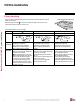
Best Practices for LG HVAC System Installation


11
Best Practices for LG HVAC System Installation
Due to our policy of continuous product innovation, some specications may change without notication.
©
LG Electronics U.S.A., Inc., Englewood Cliffs, NJ. All rights reserved. “LG” is a registered trademark of LG Corp.
Proper system operation depends on the installer using utmost care while assembling the piping system. The following pages are an over-
view of best practices when installing the refrigerant piping system.
REFRIGERANT SYSTEM ENGINEERING
LG Electronics U.S.A.,Inc., is not responsible for any piping calculations, refrigerant leaks, degradation of performance, any other potential problems
or damages caused by the interconnecting piping, their joint connections, isolation valves, or introduced debris inside the piping system.
No Pipe Size Substitutions
Use only the pipe size selected by the LATS HVAC pipe system design software. Using a different size is prohibited and may result in a
system malfunction or failure to work at all.
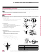
No In-line Refrigeration Components
Components such as oil traps, solenoid valves, filter-driers, sight glasses, tee fittings, and other after-market accessories are not
permitted on the refrigerant piping system between the outdoor units and the indoor / heat recovery units. Multi V systems are provided with
redundant systems that make sure oil is properly returned to the compressor. Sight-glasses and solenoid valves may cause vapor to form in
the liquid stream. Over time, driers may deteriorate and introduce debris into the system. The designer and installer should verify the refriger-
ant piping system is free of traps, sagging pipes, sight glasses, filter driers, etc.
Field-Provided Isolation Ball Valves
LG maintains a neutral position on using isolation valves in VRF refrigerant piping systems. LG does not endorse any manufacturer of isola-
tion valves. It is recognized that installing isolation valves may simplify future maintenance requirements, and, if used, considerations should
be taken including, but not limited to, the following:
• Pressure drops for any component used, including isolation valves, must be known in equivalent pipe length and calculated into the total
and segment equivalent piping lengths and compared to product design limitations.
• In all cases, materials must be suitable for the application and any applicable codes, including, but not limited to, diameter and wall thick-
ness continuity per ACR standards.
Failure to do so may cause significant performance degradation. Proper leak checks must be performed. Using isolation valves does not
automatically void any LG product warranty, however, a limited warranty may be voided in whole or part should any field supplied accessory
fail in any way that causes product failure.
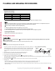
Using Elbows
Field-supplied elbows are allowed if they are long radius and designed for use with R410A refrigerant. The designer and installer, however,
should be cautious with the quantity and size of fittings used, and must account for the additional pressure losses in equivalent pipe length
calculation for each branch. The equivalent pipe length of each elbow must be added to each pipe segment in the LATS program.
Pipe Bends
When bending soft copper, use long radius bends. Refer to the “Radii of Coiled Expansion Loops and Developed Lengths of Expansion
Offsets” table for minimum radius specifications.