
Best Practices for LG HVAC System Installation


14
Best Practices for LG HVAC System Installation
Due to our policy of continuous product innovation, some specications may change without notication.
©
LG Electronics U.S.A., Inc., Englewood Cliffs, NJ. All rights reserved. “LG” is a registered trademark of LG Corp.
Refrigerant Piping System Insulation
All refrigerant piping from the outdoor unit to the indoor units must be insulated correctly for safety and usage. Y-branch connections, header
branch connections, refrigerant piping, field-provided isolation ball valves (if present), service valves, and elbows must be properly and
completely insulated using closed cell pipe insulation (up to the indoor unit piping connections). To prevent heat loss / heat gain through the
refrigerant piping, all refrigerant piping including liquid lines and vapor lines shall be insulated separately. Insulation shall be a minimum 1/2″
thick, and thickness may need to be increased based on ambient conditions and local codes. The table “Minimum Refrigerant Pipe EPDM
Insulation Wall Thickness Requirements” lists minimum wall thickness requirements for Ethylene Propylene Diene Methylene (EPDM)
insulation.
Inside the outdoor unit, maximum pipe temperature is 248°F and minimum pipe temperature is -40°F. For field insulation of refrigerant piping
between outdoor units and indoor units, consider the following pipe temperature ranges for an operating heat pump system:
• Heating mode refrigerant temperature ranges: Liquid = 75-118°F; High Pressure Vapor = 95-220°F
• Cooling mode refrigerant temperature ranges: Liquid = 75-118°F; Low Pressure Vapor = 40-90°F
All insulation joints shall be glued with no air gaps. Insulation material shall fit snugly against the refrigeration pipe with no air space between
it and the pipe. Do not allow insulation passing through pipe hangers, inside conduit, and/or sleeves to be compressed. Protect insulation
inside hangers and supports with a second layer. All pipe insulation exposed to the sun and outdoor elements shall be properly protected with
PVC, aluminum vapor barrier, or alternatively placed in a weather-resistant enclosure such as a pipe rack with a top cover; and meet local
codes.
LG-provided Y-branches and headers are shipped from the factory with pre-formed peel-and-stick foam insulation jackets, with a 1.84 lb./ft.
3
density, 1/2″ thickness, and meet UL94 MF-1 flammability.
The design engineer should perform calculations to determine if the factory-supplied insulation jackets are sufficient to meet local codes and
avoid sweating. Add additional insulation if necessary. Check the fit of the insulation jacket after the fittings and all run-out pipes are installed.
Mark all pipes at the point where the insulation jacket ends. Remove the jacket. Install field provided insulation on the run-out and main trunk
pipes first. Install the LG-provided insulation plugs on the ends of all unused header ports. Peel the adhesive glue protector slip from the
insulation jacket and install the clam-shell jacket over the fitting.
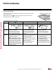
Figure 11: Typical Insulation Butt-Joint at Indoor Unit
Casing.
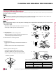
Figure 12: Typical Refrigerant Flare
Fitting Insulation Detail.
Liquid Pipe
Communication Cables
Gas Pipe
Power Wiring
Insulation
A
B
C
D
E
E
D
D
B
A
C
Surface of
Indoor Unit Casing
Field-Provided
Pipe Insulation
• Do not insulate gas and liquid pipes together as this can result in pipe leakage and malfunction due to extreme temperature fluctuations.
• Be sure to fully insulate the piping connections.
INSULATION