
Engineering Manual
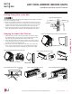
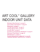

Mounting the Installation Plate
The mounting wall should be strong and solid enough to protect the unit from vibration.
• Mount the installation plate on the wall using the Type “A” screws. If mounting the unit on concrete, consider using anchor bolts.
• Always mount the installation plate horizontally. Measure the wall and mark the centerline using thread and a level.
ART COOL MIRROR INDOOR UNITS
Installation and Best Layout Practices
DANGER
To avoid the possibility of re, do not install the unit in an area where combustible gas may generate, ow, stagnate, or leak. Failure to do so will cause
serious bodily injury or death. Before beginning installation, read the safety summary at the beginning of this manual.
Select a location for installing the wall-mounted indoor unit (IDU) that meets the following conditions:
• Where there is enough structural strength to bear the weight of the unit
• Where air circulation will not be blocked
• Where noise prevention is taken into consideration
• Ensure there is sufficient space from the ceiling and floor
• Locate the indoor unit in a location where it can be easily connected to the outdoor unit/branch distribution unit
• Include space for drainage to ensure condensate flows properly out of the unit when it is in cooling mode
• Use a level indicator to ensure the unit is installed on a level plane
Note:
The unit may be damaged, may malfunction, and/or will not operate as designed if installed in any of the following conditions:
Do not install the unit where it will be subjected to direct thermal radiation from other heat sources.
Do not install the unit in an area where combustible gas may generate, flow, stagnate, or leak.
Do not install the unit in a location where acidic solution and spray (sulfur) are often used.
Do not use the unit in environments where oil, steam, or sulfuric gas are present.
Do not install additional ventilation products on the chassis of the unit.
Do not install the unit near high-frequency generator sources.
Do not install the unit near a doorway.
Installing in an Area Exposed to Unconditioned Air
In some installation applications, areas (floors, walls) in some rooms
may be exposed to unconditioned air (room may be above or next to
an unheated garage or storeroom). To countermeasure:
• Verify that carpet is or will be installed (carpet may increase the
temperature by three degrees).
• Add insulation between the floor joists.
• Install radiant heat or another type of heating system to the floor.
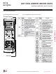
Required Clearances
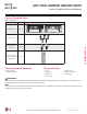
Figure 10 shows required clearance distances around a typical
installed wall-mounted unit.
>4 inches
Recommended height
>6-1/2 feet from floor
>4 inches
≥5 inches
Figure 10:Minimum Clearance Requirements.
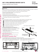
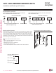
Ø2-3/4 inches
Ø2-3/4
inches
5-1/4 inches
3-3/4 inches
Right rear piping
Left rear piping
Installation Plate
Place a level on raised tab
Unit Outline
8-17/32 inches
6-7/8 inches
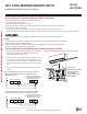
Figure 11:Installation Plate for LAN090HSV5 and LAN120HSV5 Units. Figure 12:Installation Plate for LAN180HSV5 Units.
Ø2-3/4 inches
Ø2-3/4 inches
2-23/32 inches
2-7/32 inches
Right rear
piping
Left rear
piping
Installation Plate
Measuring Tape
Measuring Tape Hanger
Place a level on raised tab
Unit Outline
8-5/32 inches
4-1/8 inches
18-1/8 inches 22-7/16 inches
Due to our policy of continuous product innovation, some specications may change without notication.
©LG Electronics U.S.A., Inc., Englewood Cliffs, NJ. All rights reserved. “LG” is a registered trademark of LG Corp.
22 | ART COOL MIRROR
Multi F and Multi F MAX Indoor Unit Engineering Manual
MULTI
F
MAX
MULTI
F