
Engineering Manual

ART COOL MIRROR INDOOR UNITS
Installation and Best Layout Practices
Power Wiring / Communications Cable Guidelines
• Follow manufacturer’s circuit diagrams in the technical manuals.
• Confirm power source specifications.
• Confirm that the electrical capacity is sufficient.
• Starting current must be maintained ±10 percent of the rated current marked on the outdoor unit name plate.
• Confirm cable thickness specifications.
• It is recommended that a circuit breaker is installed, especially if conditions could become wet or moist.
• Include a disconnect in the power wiring system, add an air gap contact separation of at least 1/8 inch in each active (phase) conductor.
• Loose wiring may cause unit to malfunction, overheat, and catch fire, resulting in severe injury or death.
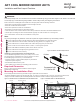
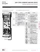
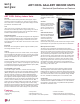
1. Insert the power wiring/communications cable from the outdoor
unit or branch distribution unit (Multi F MAX systems only)
through the bottom of the indoor unit.
2. Connect each wire to its appropriate terminal on the indoor unit
control board. Verify that the color and terminal numbers from
the outdoor unit or branch distribution unit (Multi F MAX systems
only) wiring match the color and terminal numbers on the indoor
unit.
3. Secure the power wiring/communications cable with the cable
restraint.
Terminal block
Power wiring /
communications cable
Wired Remote Controlle
r
Terminal (Optional)
Cable restraint
Connecting the Power Wiring and Communications Cable
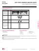
Figure 20:Connecting the Power Wiring / Communications Cable.
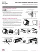
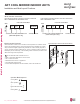
Figure 21:Simplied View of Indoor Unit to Outdoor Unit / Branch
Distribution Unit Terminal Connections—LAN090HSV5 and
LAN120HSV5 models.
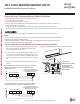
Figure 22:Simplied View of Indoor Unit to Outdoor Unit / Branch
Distribution Unit Terminal Connections—LAN180HSV5 models.
Indoor Unit Terminal Block
GND
Outdoor Unit Terminal Block or
Branch Distribution Unit Terminal Block
(Multi F MAX Systems Only)
GND
GRN / YLW
BR
BL
RD
3 or S
32(L2)1(L1)
Indoor Unit Terminal Block
1(L1 )2(L2)
GND
Outdoor Unit Terminal Block or
Branch Distribution Unit Terminal Block
(Multi F MAX Systems Only)
GND
GRN / YLW
BR
BL
RD
3
3 or S
Note:
• Terminal screws may become loose during transport. Properly tighten the terminal connections during installation.
A voltage drop may cause the following problems:
• Magnetic switch vibration, fuse breaks, or disturbance to the normal function of an overload protection device.
• Compressor will not receive the proper starting current.
Due to our policy of continuous product innovation, some specications may change without notication.
©LG Electronics U.S.A., Inc., Englewood Cliffs, NJ. All rights reserved. “LG” is a registered trademark of LG Corp.
24 | ART COOL MIRROR
Multi F and Multi F MAX Indoor Unit Engineering Manual
MULTI
F
MAX
MULTI
F