ENGLISH FRANÇAIS ESPAÑOL INSTALLATION MANUAL AIR CONDITIONER Please read this installation manual completely before installing the product. Installation work must be performed in accordance with the national wiring standards by authorized personnel only. Please retain this installation manual for future reference after reading it thoroughly. CEILING CONCEALED DUCT Original instruction MFL68821907 Rev.06_010523 www.lghvac.com www.lg.com Copyright © 2018 - 2023 LG Electronics Inc. All Rights Reserved.
IMPORTANT! Please read this instruction sheet completely before installing the product. This air conditioning system meets strict safety and operating standards. As the installer or service person, it is an important part of your job to install or service the system so it operates safely and efficiently. ! WARNING • The information contained in the manual is intended for use by a qualified service technician familiar with safety procedures and equipped with the proper tools and test instruments.
Table of contents 4 FEATURES 5 SAFETY INSTRUCTIONS 8 INSTALLATION 8 Selection of the best location 9 Ceiling dimension and hanging bolt location 10 Indoor Unit Installation 10 Wiring Connection 14 Flaring work 14 Checking the Drainage 15 Indoor Unit Drain Piping 17 DIP Switch Setting 18 Group Control Setting 22 Airborne Noise Emission 22 Limiting concentration ENGLISH TABLE OF CONTENTS 23 HOW TO SET E.S.
Features Features Air inlet vents Air outlet vents Remote Controller (Accessory) Installation Tool Name Quantity Drain hose Clamp metal 1 EA 2 EA Washer for hanging bracket Clamp (Tie Wrap) Insulation for fitting 8 EA 4 EA 1 SET (Other) • Owner's manual • Installation manual for gas pipe Shape for liquid pipe 4 Indoor Unit
Safety Instructions ! This symbol is displayed to indicate matters and operations that can cause risk. Read the part with this symbol carefully and follow the instructions in order to avoid risk. ! WARNING This indicates that the failure to follow the instructions can cause serious injury or death. ! CAUTION This indicates that the failure to follow the instructions can cause the minor injury or damage to the product. ! WARNING Installation • Do not use a defective or underrated circuit breaker.
Safety Instructions or explosion. - There is the risk of death, injury, fire or explosion. Operation • Do not let the air conditioner run for a long time when the humidity is very high and a door or a window is left open. - Moisture may condense and wet or damage furniture. • Take care to ensure that power cable could not be pulled out or damaged during operation. - There is risk of fire or electric shock. • Do not place anything on the power cable. - There is risk of fire or electric shock.
Safety Instructions CAUTION Installation • Always check for gas (refrigerant) leakage after installation or repair of product. - Low refrigerant levels may cause failure of product. • Install the drain hose to ensure that water is drained away properly. - A bad connection may cause water leakage. • Keep level even when installing the product. - To avoid vibration or water leakage. • Do not install the product where the noise or hot air from the outdoor unit could damage the neighborhoods.
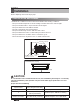
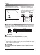
Installation Installation Read completely, then follow step by step. Selection of the best location Install the air conditioner in the location that satisfies the following conditions. • The place shall easily bear a load exceeding four times the indoor unit’s weight. • The place shall be able to inspect the unit as the figure. • The place where the unit shall be leveled. • The place shall allow easy water drainage. • The place shall easily connect with the outdoor unit.
Installation n Installation of Unit Install the unit above the ceiling correctly. E D C G POSITION OF SUSPENSION BOLT • Apply a joint-canvas between the unit and duct to absorb unnecessary vibration. • Install the unit leaning to a drainage hole side as a figure for easy water drainage. • A place where the unit will be leveled and that can support the weight of the unit. • A place where the unit can withstand its vibration. • A place where service can be easily performed.
Installation Indoor Unit Installation • Select and mark the position for fixing bolts. • Drill the hole for set anchor on the face of ceiling. • Insert the set anchor and washer onto the suspension bolts for locking the suspension bolts on the ceiling. • Mount the suspension bolts to the set anchor firmly. • Secure the installation plates onto the suspension bolts (adjust level roughly) using nuts, washers and spring washers.
Installation • Open the control box cover and connect the remote controller cables, transmission cables and indoor power cables. • Control box cover is consist of one panel. Control box cover can be separated from main body • Separate whole cover(when access from bottom of the product). Remove screws on the bottom panel and grab the both panel with two hands and pull down the whole cover.
Installation After remove the control box cover, insert cables onto the bush and conduit and then connect at terminal block. Indoor power cable Remote controller cable and transmission cable between the indoor unit and the outdoor unit L(L1) Power Supply High Voltage (208/230V) Conduit panel N(L2) GN/YL Wired Remote Transmission Controller Lock nut YL RD Conduit BK A B Conduit Hole INSULATION, OTHERS Insulate the joint and tubes completely.
Installation CAUTION The connecting cable connected to the indoor and outdoor unit should be complied with the following specifications (This equipment shall be provided with a cord set complying with the national regulation). Unit: mm (inch) 10(3/8) ± 3(1/8) 30(1-3/8) ± 5(3/16) GN /YL AWG18 20 (25 /32 ) If the supply cord is damaged, it must be replaced by a special cord or assembly available from the manufacturer of its service agent.
Installation Flaring work • Firmly hold copper pipe in a bar with the dimension shown in below table table below. • Carry out flaring work with the flaring tool. Pipe diameter Inch (mm) Ø 1/4 (Ø 6.35) Ø 3/8 (Ø 9.52) Ø 1/2 (Ø 12.7) Ø 5/8 (Ø 15.88) Ø 3/4 (Ø 19.05) A Inch (mm) Wing nut type Clutch type 0.04~0.05 (1.1~1.3) 0.06~0.07 (1.5~1.7) 0~0.02 0.06~0.07 (1.6~1.8) (0~0.5) 0.06~0.07 (1.6~1.8) 0.07~0.08 (1.9~2.1) Bar Thickness Inch (mm) 0.03 (0.7) 0.03 (0.8) 0.03 (0.8) 0.04 (1.0) 0.04 (1.
Installation • Drain piping must have down-slope (1/50 to 1/100): be sure not to provide up-and-down slope to prevent reversal flow. • During drain piping connection, be careful not to exert extra force on the drain port on the indoor unit. • The outside diameter of the drain connection on the indoor unit is 32 mm (1-1/8 inch).
Installation ! CAUTION After the confirmation of the above conditions, prepare the wiring as follows: 1) Never fail to have an individual power specialized for the air conditioner. As for the method of wiring, be guided by the circuit diagram posted on the inside of control box cover. 2) Provide a circuit breaker switch between power source and the unit.
Installation ENGLISH DIP Switch Setting 1. Indoor Unit SW1 SW2 Function Description Communication N/A (Default) Cycle N/A (Default) SW3 Group Control Selection of Master or Slave SW4 Dry Contact Mode Selection of Dry Contact Mode SW5 Installation SW6 Fan continuous operation Heater linkage N/A Ventilator linkage SW7 SW8 ! Selection of Ventilator linkage Vane selection Selection of up/down (Console) side Vane Region selection Etc.
Installation Group Control Setting ! CAUTION If you want to use the two setpoint function, you should be installed the both new thermostat and 4 series products. * Model name of wired remote controller called New thermostat : PREMTC00U 1. Group Control 1 n Wired remote controller 1 + Standard Indoor Units LGAP Network System or Master Slave Slave Slave GND Signal 12 V Only connect serial signal and GND lines between indoor units.
Installation h It is possible to connect indoor units since Feb. 2009. h It can be the cause of malfuctions when there is no setting of master and slave. h In case of Group Control, it is possible to use following functions. - Selection of operation, stop or mode - Temperature setting and room temperature check - Current time change - Control of flow rate (High/Middle/Low) - Reservation settings It is not possible to use some functions. 2.
Installation 3. Group Control 3 n Mixture connection with indoor units and Fresh Air Intake Unit LGAP Network System or FAU Master FAU Slave Master GND Signal 12 V Slave N M Display Error Message Display Error Message Master Master h In case of connecting with standard indoor unit and Fresh Air Intake Unit, separate Fresh Air Intake Unit with standard units. (N, M ≤ 16) (Because setting temperature are different.) h Other than those, it is same with Group Control 1.
Installation ENGLISH 4. 2 Remote Control n Wired remote controller 2 + Indoor unit 1 LGAP Network System or Slave Master Slave Slave GND Signal 12 V Display Error Message Master Slave 1. It is possible to connect two wired remote controllers (Max.) with one indoor unit. Set only one indoor unit to Master, set the others to Slave. Set only one wired remote controller to Master, set the others to Slave. 2. Every types of indoor unit is possible to connect two remote controller. 3.
Installation Airborne Noise Emission The A-weighted sound pressure emitted by this product is below 70 dB. ** The noise level can vary depending on the site. The figures quoted are emission level and are not necessarily safe working levels. Whilst there is a correlation between the emission and exposure levels, this cannot be used reliably to determine whether or not further precautions are required.
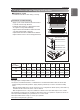
How to Set E.S.P? ENGLISH How to Set E.S.P? M1 Chassis : 7, 9, 12, 15, 18 k Setting value 60 65 70 75 80 85 90 95 100 105 110 115 120 125 130 135 140 2.5(0.10) 6.6(233) 8.9(315) 11.3(400) 12.9(455) 14.7(520) 16.4(580) 18.1(640) 19.7(696) 20.9(737) 23.1(816) 24.4(860) 4(0.16) 8.1(285) 10.4(368) 12.5(440) 14.3(504) 16.1(569) 17.9(631) 19.3(681) 21.4(755) 22.9(809) 24.3(858) 6(0.24) 6.1(216) 8.4(296) 10.4(366) 12.9(454) 15.0(530) 16.9(598) 18.9(666) 20.7(731) 22.3(786) 23.
How to Set E.S.P? M2 (7k~24k) (Unit: CMM(CFM)) Setting Value 75 80 85 90 95 100 105 110 115 120 125 130 135 140 145 150 155 4(0.16) 15.0(530) 19.0(672) 24.9(879) 27.6(974) 30.4(1 073) 33.1(1 168) 35.9(1 267) 38.6(1 363) 40.1(1 416) 6(0.24) 7.5(267) 13.7(486) 20.4(720) 24.4(861) 28.7(1 013) 31.7(1 119) 34.7(1 225) 37.8(1 334) 39.1(1 380) 8(0.31) 4.9(173) 7.8(276) 15.7(554) 20.8(734) 24.1(851) 30.5(1 077) 33.8(1 193) 37.1(1 310) 38.5(1 358) Static Pressure (mmAq(in wg)) 10(0.39) 12(0.47) 5.2(182) 9.
How to Set E.S.P? (Unit: CMM(CFM)) Setting Value 70 75 80 85 90 95 100 105 110 115 120 125 130 135 4(0.16) 25.2(891) 30.4(1 074) 35.0(1 235) 39.8(1 404) 44.3(1 562) 49.3(1 741) 53.0(1 872) 57.2(2 020) 6(0.24) 21.4(756) 27.1(959) 35.4(1 250) 40.1(1 416) 44.8(1 581) 49.4(1 744) 54.1(1 910) 58.8(2 076) 8(0.31) 18.5(654) 24.6(869) 31.5(1 111) 36.8(1 300) 44.6(1 574) 49.2(1 737) 53.9(1 903) 58.6(2 069) Static Pressure (mmAq(in wg)) 10(0.39) 12(0.47) 14(0.55) 22.7(800) 28.8(1 017) 35.4(1 251) 43.
How to Set E.S.P? How to Set Auto ESP (Air conditioner) • This function automatically sets the rotation speed of the fans corresponding to each step of rated airflow for easy installation. • Auto ESP setting is required by remote control ※ For details, refer to the remote control manual 1. If B button is pressed so long for over 3 seconds, it enters to the installer setting mode. 2. Use the F G buttons to enter 68-02 and set the Value2 value. Refer to the table below for Value2 values.
How to Set E.S.P? 1. Enter the installer mode on the remote control and select Auto ESP. 2. Select the setting category, and press [∧(up)] button for 3 seconds to enter the password input screen for the installer setting. 3. Input the password and press [OK] button to move to the installer setting list. And Selet Auto ESP 4. After selecting “Manual”, set the Voltage(190V - 270V) as shown in the screen. 5. It takes about 3-8 minutes to set, and you can see the setting result as Pass or Fail.
Indoor Unit
US CANADA Please call the installing contractor of your product, as warranty service will be provided by them.