ENGLISH FRANÇAIS AIR CONDITIONER • Please read this installation manual completely before installing the product. • Installation work must be performed in accordance with the national wiring standards by authorized personnel only. • Please retain this installation manual for future reference after reading it thoroughly. TYPE: Ceiling Cassette - 1Way P/NO : MFL42803113 http://www.lghvac.com www.lg.
IMPORTANT! Please read this instruction sheet completely before installing the product. This air conditioning system meets strict safety and operating standards. As the installer or service person, it is an important part of your job to install or service the system so it operates safely and efficiently. WARNING • Installation or repairs made by unqualified persons can result in hazards to you and others.
Ceiling Cassette - 1Way Type Indoor Unit Installation Manual TABLE OF CONTENTS Installation Requirements Required Parts Required Tools Installation Parts ....................4 Safety Precautions.................5 Installation Ceiling dimension and hanging bolt location ......................9 Wiring Connection ...............
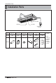
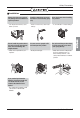
Installation Parts Installation Parts Anti-bacteria filter TEMP Remote Controller Air Outlet Air Intake Wired Remote Controller Name Drain hose Clamp metal Washer for hanging backet Plastic band Insulation for fitting Conduit mounting plate Quantity 1 EA 2 EA 8 EA 4 EA 1 SET 1 EA Shape for gas pipe for liquid pipe 4 Indoor Unit (Other) • Paper pattern for installation • Owner's manual • Installation manual
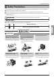
Safety Precautions Safety Precautions To prevent injury to the user or other people and property damage, the following instructions must be followed. ■ Be sure to read before installing the air conditioner. ■ Be sure to observe the cautions specified here as they include important items related to safety. ■ Incorrect operation due to ignoring instruction will cause harm or damage. The seriousness is classified by the following indications. This symbol indicates the possibility of death or serious injury.
Safety Precautions Do not modify or extend the power cable. Do not let the air conditioner run for a long time when the humidity is very high and a door or a window is left open. Be cautious when unpacking and installing the product. • There is risk of fire or electric shock. • Moisture may condense and wet or damage furniture. • Sharp edges could cause injury. Be especially careful of the case edges and the fins on the condenser and evaporator.
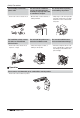
Safety Precautions ■ Installation Always check for gas (refrigerant) leakage after installation or repair of product. Install the drain hose to ensure that water is drained away properly. Keep level even when installing the product. • Low refrigerant levels may cause failure of product. • A bad connection may cause water leakage. • To avoid vibration or water leakage. 90 Use two or more people to lift and transport the product.
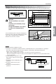
Installation Installation Read completely, then follow step by step. Selection of the best location Above 2500(98-7/16) 3300(129-15/16) or less 500(19-11/16) or more 1000(39-3/8) or more Ceiling Ceiling Board Ceiling Board 500(19-11/16) or more 300(11-13/16) or less 200(7-7/8) or more • There should not be any heat source or steam near the unit. • There should not be any obstacles to the air circulation. • A place where air circulation in the room will be good.
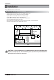
Installation Ceiling dimension and hanging bolt location • The dimensions of the paper model for installation are the same as those of the ceiling opening dimensions. 1,030(40-1/2) (Ceiling opening) Ceiling 57(2-1/4) • Select and mark the position for fixing bolts and piping hole. • Decide the position for fixing bolts slightly tilted to the drain direction after considering the direction of drain hose. • Drill the hole for anchor bolt on the wall.
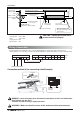
Ceiling 55mm (2-3/16 inch) Installation Air Conditioner body Ceiling board Keep the length of the bolt from the bracket to 40mm(1-1/2 inch) Hanging bolt (W3/8 or M10) Nut (W3/8 or M10) Flat washer for M10 (accessory) Ceiling board Spring washer (M10) Flat washer for M10 (accessory) Nut (W3/8 or M10) Set screw of paper model (4 pieces) Paper model for installation Open the ceiling board along the outer edge of the paper model Adjust the same height • The following parts are local purchasing.
Installation Installation of Decoration Panel Before installing the decoration panel, always remove the paper template. The decoration panel has its installation direction. 1. Temporarily fix two decoration panel fixing screws (hexagon M5 screw) on the unit body. (Tighten by amount 10mm in length.) The fixing screws (hexagon M5 screw) are included the indoor unit box. 2. Remove the air inlet grille from the decoration panel. (Remove the hook for the air inlet grille cord.) 3.
Installation Drain Piping • Drain piping must have down-slope (1/50 to 1/100): be sure not to provide up-and-down slope to prevent reversal flow. • During drain piping connection, be careful not to exert extra force on the drain port on the indoor unit. • The outside diameter of the drain connection on the indoor unit is 32mm(1-1/4 inch).
Installation CAUTION: After the confirmation of the above conditions, prepare the wiring as follows: 1) Never fail to have an individual power specialized for the air conditioner. As for the method of wiring, be guided by the circuit diagram posted on the inside of control box cover. 2) Provide a circuit breaker switch between power source and the unit.
Installation Installation of Wired Remote Controller 1. Please fix tightly using provided screw after placing remote controller setup board on the place where you like to setup. - Please set it up not to bend because poor setup could take place if setup board bends. Please set up remote controller board fit to the reclamation box if there is a reclamation box. 2. Can set up Wired remote controller cable into three directions.
Installation 4. Please connect indoor unit and remote controller using connection cable. Please check if connector is normally connected. Indoor Unit side Connecting cable 5. Please use extension cable if the distance between wired remote controller and indoor unit is more than 10m. Installation Manual 15 ENGLISH When installing the wired remote controller, do not bury it in the wall. (It can cause damage in the temperature sensor.) Do not install the cable to be 50m or above.
Installation Name and function of wired remote controller(Accessory) 1 10 9 8 2 3 7 4 11 12 13 5 6 14 15 Please attach the inform label inside of the door. Please choose proper language depend on your country. 1. Operation indication screen 2. Set temperature button • It will set not room temperature but outlet air temperature. 3. Fan speed button • Fan Speed have 3 Steps. • Middle and Low step is same 4. ON/OFF button 5. Opration mode selection button 6.
Installation Dip Switch Setting of Indoor unit PCB Function SW1 Communication Description N/A (Default) SW2 Cycle N/A (Default) SW3 Group Control Selection of Master or Slave SW4 Dry Contact Mode Selection of Dry Contact Mode Setting Off - Setting On - - - Off Master Slave Off Wired/Wireless remote controller Selection of Manual or Auto operation Mode Auto Off Continuous operation Removall - Off Off Installation Fan continuous operation SW6 Heater linkage N/A - - SW7 Ventila
Installation Group Control Setting 1. Group Control 1 ■ Wired remote controller 1 + Indoor units LGAP Network System Master Slave Slave Slave GND Signal 12 V Display Error Message Only connect serial signal and GND lines between slave indoor unit Master ■ Dip Switch in PCB (Cassette and Duct Type indoor units) Master Setting - No. 3 Off Slave Setting - No. 3 On 1. It is possible to 16 indoor units(Max) by one wired remote controller. Set only one indoor unit to Master, set the others to Slave. 2.
Installation 5. In case of any error occurs at indoor unit, display on the wired remote controller. Exception of the error indoor unit, an individual indoor unit control possibility. 6. In case of Group Control, it is possible to use following functions. - Selection of operation options (operation/stop/mode/set temperature) - Control of flow rate (High/Middle/Low) - It is not possible at some functions. ❈ Master/Slave setting of indoor units be set possible using a PCB Dip Switch.
Installation 3. Group Control 3 ■ Mixture connection with indoor units and Fresh Air Intake Unit LGAP Network System FAU Master FAU Slave Master Slave GND Signal 12 V Display Error Message Master Master ❈ In case of connecting with standard indoor unit and Fresh Intake Unit, separate Fresh Air Intake Unit with standard units. (Because setting temperature are different.) ❈ Other than those, it is same with Group Control 1.
Installation 4. 2 Remote Control ■ Wired remote controller 2 + Indoor unit 1 LGAP Network System Master ENGLISH Display Error Message Master Slave 1. It is possible to connect two wired remote controllers with one indoor unit. 2. Every types of indoor unit is possible to connect two remote controller. 3. It is possible to use wireless remote controller at the same time. 4. It is possible to connect with Dry Contact and Central controller at the same time. 5.
5. Accessories for group control setting It is possible to set group control by using below accessories.
US 1. Please call the installing contractor of your product, as warranty service will be provided by them. 2. If you have service issues that have not been addressed by the contractor, please call 1-888-865-3026.