ENGLISH FRANÇAIS ESPAÑOL INSTALLATION MANUAL AIR CONDITIONER • Please read this installation manual completely before installing the product. • Installation work must be performed in accordance with the national wiring standards by authorized personnel only. • Please retain this installation manual for future reference after reading it thoroughly. TYPE : Ceiling Cassette - 4Way http://www.lghvac.com www.lg.
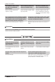
IMPORTANT! Please read this instruction sheet completely before installing the product. This air conditioning system meets strict safety and operating standards. As the installer or service person, it is an important part of your job to install or service the system so it operates safely and efficiently. • Installation or repairs made by unqualified persons can result in hazards to you and others.
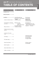
Ceiling Cassette - 4Way Type Indoor Unit Installation Manual Installation Requirements Required Parts Required Tools Installation Parts.......................4 Safety Precautions ...................5 Installation.................................7 Selection of the best location...7 Ceiling dimension and hanging bolt location .............................8 Wiring Connection ...................
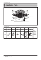
Installation Parts Installation Parts Anti-bacteria filter Air Outlet Air Intake Wired Remote Controller(Accessory) Installation Tool Name Drain hose Clamp metal Washer for hanging backet Plastic band Insulation for fitting Conduit mounting plate Quantity 1 EA 2 EA 8 EA 4 EA 1 SET 1 EA Shape for gas pipe for liquid pipe • Screws for fixing panels are attached to decoration panel.
Safety Precautions To prevent injury to the user or other people and property damage, the following instructions must be followed. n Be sure to read before installing the air conditioner. n Be sure to observe the cautions specified here as they include important items related to safety. n Incorrect operation due to ignoring instruction will cause harm or damage. The seriousness is classified by the following indications. This symbol indicates the possibility of death or serious injury.
Safety Precautions For installation, always contact the dealer or an Authorized Service Center. • There is risk of fire, electric shock, explosion, or injury. Do not install the product on a defective installation stand. Be sure the installation area does not deteriorate with age. • It may cause injury, accident, or damage to the product. • If the base collapses, the air conditioner could fall with it, causing property damage, product failure, and personal injury.
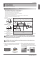
Installation ENGLISH Installation Read completely, then follow step by step. Selection of the best location • There should not be any heat source or steam near the unit. • There should not be any obstacles to the air circulation. • A place where air circulation in the room will be good. • A place where drainage can be easily obtained. • A place where noise prevention is taken into consideration. • Do not install the unit near the door way.
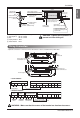
Installation Ceiling dimension and hanging bolt location • The dimensions of the paper model for installation are the same as those of the ceiling opening dimensions. Ceiling Ceiling board Level gauge TM/TN/TP Chassis TQ/TR Chassis 585~660(23~26)(Ceiling opening) 875(34-7/16) (Ceiling opening) 787(30-15/16) 517(20-3/8) 461(18-1/8) Unit:mm(inch) CAUTION : • This air-conditioner uses a drain pump. • Install the unit horizontally using a level gauge.
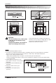
Installation Nut (W3/8 or M10) 105 mm (4-1/8 inch) 15 mm (19/32 inch) Flat washer for M10 (accessory) Ceiling board Spring washer (M10) Air Conditioner body Ceiling board Keep the length of 105 mm(4-1/8 inch), 15 mm(19/32 inch) between the air conditioner bottom surface and the ceiling surface Flat washer for M10 (accessory) Nut (W3/8 or M10) Set screw of paper model (4 pieces) Paper model for installation Open the ceiling board along the outer edge of the paper model • The following parts are loc
Installation Connection method of the connecting cable(Example) 1(L1) 2(L2) 3(A) 4(B) L(L1) Power Supply High Voltage (208/230V) N(L2) L(L3) Power Supply High Voltage (208/230 V) Lock nut Conduit N(L4) Lock nut Conduit mounting plate • TQ/TR Chassis Conduit Conduit mounting plate • TM/TN/TP Chassis WARNING : Loose wiring may cause the terminal to overheat or result in unit malfunction. A fire hazzard may also exist. Therefore, be sure all wiring is tightly connected.
Installation ENGLISH Plumbing materials and storage methods Pipe must be able to obtain the specified thickness and should be used with low impurities. Also when handling storage, pipe must be careful to prevent a fracture, deformity and wound. Should not be mixed with contaminations such as dust, moisture. Refrigerant piping on three principles Drying Should be no moisture inside Items Moisture Cleanliness No dust inside.
Installation Nitrogen substitution method Welding, as when heating without nitrogen substitution a large amount of the oxide film is formed on the internal piping. The oxide film is a caused by clogging EEV, Capillary, oil hole of accumulator and suction hole of oil pump in compressor. It prevents normal operation of the compressor. In order to avoid this problem, Welding should be done after replacing air by nitrogen gas. When welding plumbing pipe, the work is required.
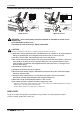
Installation Before installing the decoration panel, always remove the paper template. The decoration panel has its installation direction. 1. Temporarily fix two decoration panel fixing screws (hexagon M5 screw) on the unit body. (Tighten by amount 10mm(3/8 inch) in length. The fixing screws (hexagon M5 screw) are included the indoor unit box. 2. Remove the air inlet grille from the decoration panel. (Remove the hook for the air inlet grille cord.) 3.
Installation Drain Piping • Drain piping must have down-slope (1/50 to 1/100): be sure not to provide up-and-down slope to prevent reversal flow. • During drain piping connection, be careful not to exert extra force on the drain port on the indoor unit. • The outside diameter of the drain connection on the indoor unit is 32 mm(1-1/4 inch).
Installation Attention 1/50~1/100 2. Keep the drain hose downward up to 1/50~1/100 inclination. Prevent any upward flow or reverse flow in any part. MAX 700 mm (27-9/16 inch) 3. 5 mm (3/16 inch) or thicker formed thermal insulator is provided for the drain pipe. Thermal insulator (Local supply) Drain pipe (Local supply) Unit Elbow 4. Upward routing is not allowed. Drain pump 5. Be sure to check the drain pump for normal operation and abnormal noise when electrical wiring is complete.
Installation DIP Switch Setting 1.
Installation ENGLISH Group Control Setting 1. Group Control 1 n Wired remote controller 1 + Standard Indoor Units LGAP Network System or Master Slave Slave Slave GND Signal 12 V Only connect serial signal and GND lines between indoor units. Display Error Message Master n DIP Switch in PCB ¿ Master Setting - No. 3 Off ¡ Slave Setting - No. 3 On Indoor Unit DIP Switch Some products have no DIP switch on PCB.
Installation h It is possible to connect indoor units since Feb. 2009. h It can be the cause of malfuctions when there is no setting of master and slave. h In case of Group Control, it is possible to use following functions. - Selection of operation, stop or mode - Temperature setting and room temperature check - Current time change - Control of flow rate (High/Middle/Low) - Reservation settings It is not possible to use some functions.
Installation 3. Group Control 3 ENGLISH n Mixture connection with indoor units and Fresh Air Intake Unit LGAP Network System or FAU Master FAU Slave Master GND Signal 12 V Slave N M Display Error Message Display Error Message Master Master h In case of connecting with standard indoor unit and Fresh Air Intake Unit, separate Fresh Air Intake Unit with standard units. (N, M ≤ 16) (Because setting temperature are different.) h Other than those, it is same with Group Control 1.
Installation 4. 2 Remote Control n Wired remote controller 2 + Indoor unit 1 LGAP Network System or Slave Master Slave Slave GND Signal 12 V Display Error Message Master Slave 1. It is possible to connect two wired remote controllers (Max.) with one indoor unit. Set only one indoor unit to Master, set the others to Slave. Set only one wired remote controller to Master, set the others to Slave. 2. Every types of indoor unit is possible to connect two remote controller. 3.
Installation 5. Accessories for group control setting Indoor unit 2 EA +Wired remote controller h PZCWRCG3 cable used for connection Indoor unit 1 EA +Wired remote controller 2 EA h PZCWRC2 cable used for connection Slave Master PZCWRC2 PZCWRCG3 Master Master Slave • Apply totally enclosed noncombustible conduit in case of local building code Requiring plenum cable usage. Installation Manual 21 ENGLISH It is possible to set group control by using below accessories.
Installation Model Designation ARN U 48 3 TM C 4 Serial Number Combinations of functions A:Basic function L: Neo Plasma(Wall Mounted) C: Plasma(Ceiling Cassette) G: Low Static K: High Sensible Heat U: Floor Standing without Case SE/S8 - R: Mirror V: Silver B:Blue(ART COOL Type Panel Clolr) SF - E: Red V: Silver G:Gold 1: Kiss (Photo changeable) Q: Console Z: Fresh Air Intake Unit Chassis Name Electrical Ratings 1:1 Ø, 115 V, 60 Hz 6:1 Ø, 220 - 240 V, 50 Hz 3:1 Ø, 208/230 V, 60 Hz 2:1 Ø, 220 V, 60 Hz
US 1. Please call the installing contractor of your product, as warranty service will be provided by them. 2. If you have service issues that have not been addressed by the contractor, please call 1-888-865-3026.