ENGLISH FRANÇAIS ESPAÑOL INSTALLATION MANUAL AIR CONDITIONER • Please read this installation manual completely before installing the product. • Installation work must be performed in accordance with the national wiring standards by authorized personnel only. • Please retain this installation manual for future reference after reading it thoroughly.your set and retain it for future reference. P/NO : MFL68460502 http://www.lghvac.com www.lg.
TIPS FOR SAVING ENERGY ENGLISH TIPS FOR SAVING ENERGY Here are some tips that will help you minimize the power consumption when you use the air conditioner. You can use your air conditioner more efficiently by referring to the instructions below: • Do not cool excessively indoors. This may be harmful for your health and may consume more electricity. • Block sunlight with blinds or curtains while you are operating the air conditioner.
IMPORTANT SAFETY INSTRUCTIONS 3 READ ALL INSTRUCTIONS BEFORE USING THE APPLIANCE. Always comply with the following precautions to avoid dangerous situations and ensure peak performance of your product ! WARNING It can result in serious injury or death when the directions are ignored ! CAUTION It can result in minor injury or product damage when the directions are ignored ! WARNING • Installation or repairs made by unqualified persons can result in hazards to you and others.
IMPORTANT SAFETY INSTRUCTIONS ENGLISH • Use a vacuum pump or Inert(nitrogen) gas when doing leakage test or air purge. Do not compress air or Oxygen and do not use Flammable gases. Otherwise, it may cause fire or explosion. - There is the risk of death, injury, fire or explosion. • When installing and moving the air conditioner to another site, do not charge it with a different refrigerant from the refrigerant specified on the unit.
IMPORTANT SAFETY INSTRUCTIONS 5 Installation • Always check for gas (refrigerant) leakage after installation or repair of product. - Low refrigerant levels may cause failure of product. • Do not install the product where the noise or hot air from the outdoor unit could damage the neighborhoods. - It may cause a problem for your neighbors. • Keep level even when installing the product. - To avoid vibration or water leakage. • Do not install the unit where combustible gas may leak.
IMPORTANT SAFETY INSTRUCTIONS ENGLISH • Safely dispose of the packing materials. - Packing materials, such as nails and other metal or wooden parts, may cause stabs or other injuries. - Tear apart and throw away plastic packaging bags so that children may not play with them. If children play with a plastic bag which was not torn apart, they face the risk of suffocation. • Turn on the power at least 6 hours before starting operation.
TABLE OF CONTENTS 7 ENGLISH TABLE OF CONTENTS 2 3 8 9 TIPS FOR SAVING ENERGY IMPORTANT SAFETY INSTRUCTIONS INSTALLATION PROCESS OUTDOOR UNITS INFORMATION 12 ALTERNATIVE REFRIGERANT R410A 13 SELECT THE BEST LOCATION 15 INSTALLATION SPACE 15 Individual Installation 17 LIFTING METHOD 18 INSTALLATION 18 19 20 23 The location of the Anchor bolts Foundation for Installation Preparation of Piping Plumbing materials and storage methods 25 REFRIGERANT PIPING 25 26 26 27 28 28 29 46 50 52 53 54 ELECTRICAL
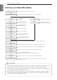
INSTALLATION PROCESS ENGLISH INSTALLATION PROCESS Determination of division work Preparation of contract drawings Sleeve and insert work Installation of indoor unit Indicate clearly who will be responsible for switch setting. Make connection clearly between outdoor, indoor, remote controller and option.
OUTDOOR UNITS INFORMATION 9 ENGLISH OUTDOOR UNITS INFORMATION ! CAUTION Combination Ration (50~130%) Outdoor Number Connection Ratio Single outdoor units 130% Double outdoor units 130% Triple outdoor units 130% Notes : * We can guarantee the operation only within 130% Combination. Power Supply : 3Ø, 575V, 60Hz Model Name : ARUB***CTE4 Unit HP Ton Model Name Combination Unit Independent Unit UX2 8 6 ARUB072CTE4 UX3 10 8 ARUB096CTE4 UX3 12 10 ARUB121CTE4 kg 7.7 10.7 10.7 lbs 16.9 23.6 23.
OUTDOOR UNITS INFORMATION ENGLISH Unit HP Ton Model Name Combination Unit Independent Unit kg lbs Number of maxmum connectable indoor units kg Net Weight lbs Refrigerant Precharged Amount mm Dimensions (WxHxD) inch UX3+UX3 UX3+UX3 24 26 20 22 ARUB240CTE4 ARUB264CTE4 ARUB144CTE4 ARUB144CTE4 ARUB096CTE4 ARUB121CTE4 21.4 21.4 47.2 47.2 39 42 (245 × 1) + (285 × 1) (245 × 1) + (285 × 1) (540 × 1) + (628 × 1) (540 × 1) + (628 × 1) (1,240×1,680×760)×2 (1,240×1,680×760)×2 (48.8×66.1×29.9)×2 (48.8×66.1×29.
OUTDOOR UNITS INFORMATION Combination Unit Model Name Independent Unit kg lbs Number of maxmum connectable indoor units Refrigerant Precharged Amount UX3+UX3+UX3 36 30 ARUB360CTE4 ARUB144CTE4 ARUB121CTE4 ARUB096CTE4 32.1 70.8 58 kg (245 × 2) + (285 × 1) lbs (540 × 2) + (628 × 1) mm (1,240×1,680×760)×3 inch (48.8×66.1×29.9)×3 Net Weight Dimensions (WxHxD) Liquid Pipes mm(inch) Pipe ConLow Pressure Gas Pipes mm(inch) nections High Pressure Gas Pipes mm(inch) 19.05(3/4) 41.3(1 5/8) 28.
ALTERNATIVE REFRIGERANT R410A ENGLISH ALTERNATIVE REFRIGERANT R410A The refrigerant R410A has the property of higher operating pressure in comparison with R22. Therefore, all materials have the characteristics of higher resisting pressure than R22 ones and this characteristic should be also considered during the installation. R410A is an azeotrope of R32 and R125 mixed at 50:50, so the ozone depletion potential (ODP) of R410A is 0.
SELECT THE BEST LOCATION 13 Select space for installing outdoor unit, which will meet the following conditions: • No direct thermal radiation from other heat sources • No possibility of annoying neighbors by noise from unit • No exposition to strong wind • With strength which bears weight of unit • Note that drain flows out of unit when heating • With space for air passage and service work shown next • Because of the possibility of fire, do not install unit to the space where generation, inflow, stagnation
SELECT THE BEST LOCATION ENGLISH [Unit : mm(inch)] 481(18-15/16) 7 345(13-19/32) 100(3-15/16) more (Serviceing space) 300(11-13/16) more 300(11-13/16) more (Servicing space) 1 (Servicing space) 2 3 450(17-23/32) 100(3-15/16) more (Serviceing space) Inspection door (servicing space) 450(17-23/32) more 300(11-13/16) more (Servicing space) (Servicing space) 450(17-23/32) 453(17-27/32) 60(2-3/8) 5 6 61(2-13/32) 419(16-1/2) 137(5-13/32) 174(6-27/32) 30(1-3/16) 174(6-27/32) 4 128(5-
INSTALLATION SPACE 15 ENGLISH INSTALLATION SPACE Individual Installation During the installation of the unit, consider service, inlet, and outlet and acquire the minimum space as shown in the figures below.
INSTALLATION SPACE ENGLISH Seasonal wind and cautions in winter • Sufficient measures are required in a snow area or severe cold area in winter so that product can be operated well. • Get ready for seasonal wind or snow in winter even in other areas. • Install a suction and discharge duct not to let in snow or rain. • Install the outdoor unit not to come in contact with snow directly. If snow piles up and freezes on the air suction hole, the system may malfunction.
LIFTING METHOD 17 • When carrying the suspended, unit pass the ropes under the unit and use the two suspension points each at the front and rear. • Always lift the unit with ropes attached at four points so that impact is not applied to the unit. • Attach the ropes to the unit at an angle of 40° or less. Locking points for transportation ropes Forklift Carrying Hole Forklift Carrying Guide ! CAUTION Be very careful while carrying the product.
INSTALLATION • The outdoor unit supports at the bottom shall have width of at least 100mm(3-15/16 inch) under the Unit’s legs before being fixed. • The outdoor unit supports should nave minimum height of 200mm(7-7/8 inch). • Anchor bolt must be inserted at least 75mm(2-15/16 inch). m 00m ast 1 h) At le /16 inc 5 (3-1 For outdoor units should not be supported only by the corner supports.
INSTALLATION 19 • Fix the unit tightly with bolts as shown below so that unit will not fall down due to earthquake or gust. • Use the H-beam support as a base support • Noise and vibration may occur from the floor or wall since vibration is transferred through the installation part depending on installation status. Thus, use anti-vibration materials (cushion pad) fully (The base pad shall be more than 200mm(7.87inch)). At least 200 (7.87) 200(7.87) 75(2.95) 200(7.87) 75(2.95) 100(3.
INSTALLATION ENGLISH Preparation of Piping Main cause of gas leakage is defect in flaring work. Carry out correct flaring work in the following procedure. Cut the pipes and the cable - Use the accessory piping kit or the pipes purchased locally. - Measure the distance between the indoor and the outdoor unit. - Cut the pipes a little longer than measured distance. - Cut the cable 1.5m(4.92ft) longer than the pipe length.
INSTALLATION 21 ENGLISH Flare shape and flare nut tightening torque Precautions when connecting pipes - See the following table for flare part machining dimensions. - When connecting the flare nuts, apply refrigerant oil to the inside and outside of the flares and turn them three or four times at first. (Use ester oil or ether oil.) - See the following table for tightening torque.(Applying too much torque may cause the flares to crack.
INSTALLATION ENGLISH Closing shutoff valve 1 Remove the cap and turn the valve clockwise with the hexagon wrench. 2 Securely tighten the valve until the shaft contacts the main body seal. 3 Make sure to tighten the cap securely. * For the tightening torque, refer to the table on the below. Tightening torque Shut off valve size [mm(inch)] Ø6.35(1/4) Ø9.52(3/8) Ø12.7(1/2) Ø15.88(5/8) Ø19.
INSTALLATION 23 Pipe must be able to obtain the specified thickness and should be used with low impurities. Also when handling storage, pipe must be careful to prevent a fracture, deformity and wound. Should not be mixed with contaminations such as dust, moisture. Refrigerant piping on three principles Items Drying Cleanliness Airtight Should be no moisture inside No dust inside.
INSTALLATION Welding, as when heating without nitrogen substitution a large amount of the oxide film is formed on the internal piping. The oxide film is a caused by clogging EEV, Capillary, oil hole of accumulator and suction hole of oil pump in compressor. It prevents normal operation of the compressor. In order to avoid this problem, Welding should be done after replacing air by nitrogen gas. When welding plumbing pipe, the work is required. Regulator Welding Point Nitrogen gas Pressure 0.02Mpa (2.
REFRIGERANT PIPING INSTALLATION 25 Precautions on Pipe connection / Valve operation Pipe connection is done by connecting from the end of the pipe to the branching pipes, and the refrigerant pipe coming out of the outdoor unit is divided at the end to connect to each indoor unit and HR unit. Flare connection for the indoor unit, and welding connection for the outdoor pipe and the branching parts. (Including HR unit) - Use hexagonal wrench to open/close the valve.
REFRIGERANT PIPING INSTALLATION ENGLISH Connection of Outdoor units (Unit : mm(inch)) Outdoor units Model Low Pressure Gas Pipe Liquid Pipe I.D.28.58(1-1/8) High Pressure Gas Pipe I.D31.8(1-1/4) I.D28.58(1-1/8) I.D25.4(1) I.D34.9(1-3/8) I.D31.8(1-1/4) 331(13-1/32) 314(12-3/8) I.D.15.88(5/8) I.D.15.88(5/8) 416(16-3/8) 408(16-1/16) I.D.28.58(1-1/8) I.D31.8(1-1/4) 111 I.D25.4(1) (4-3/8) I.D28.58(1-1/8) I.D28.58(1-1/8) I.D.31.8(1-1/4) C ARCNB21 C 2 Unit I.D.22.2(7/8) I.D.34.
REFRIGERANT PIPING INSTALLATION 27 ENGLISH Installation of Outdoor Unit, HR Unit and Indoor Unit Refrigerant Pipe 3 pipes are connected to the HR unit from the outdoor unit, classified into liquid pipe, low pressure gas pipe and high pressure gas pipe depending on status of refrigerant passing through the pipe. You must connect 3 pipes from outdoor unit to HR unit. For connection between indoor unit and HR unit, you must connect both liquid pipe and gas pipe from the HR unit to the indoor unit.
REFRIGERANT PIPING INSTALLATION ENGLISH Type of HR Unit Select an HR unit according to the number of the indoor units to be installed. HR units are classified into 3 types by the number of connectable indoor units. Ex) Installation of 6 indoor units Consists of HR unit for 4 branches and HR unit for 2 branches.
REFRIGERANT PIPING INSTALLATION 29 ENGLISH Installation of Zoning Control Some indoor unit can be connected to one port of HR unit. HR unit Zoning control group 1 HR unit sealing Zoning control group 2 (Max. 8 Indoor Units) (Max. 8 Indoor Units) Changeover under control Auto changeover Changeover under control ! WARNING • A branch pipe of HR unit allows up to 14.5kW(48kBtu/h) based on cooling capacity of the indoor unit. (up to 14.
REFRIGERANT PIPING INSTALLATION ENGLISH [Reducers for indoor unit and HR unit] Unit : mm(inch) Gas pipe Models Indoor unit reducer Liquid pipe High pressure Low pressure OD9.52(3/8) Ø6.35(1/4) OD15.88(5/8) OD19.05(3/4) Ø15.88(5/8) Ø12.7(1/2) PRHR021A Ø12.7(1/2) OD22.2(7/8) Ø19.05(3/4) Ø15.88(5/8) OD9.52(3/8) Ø6.35(1/4) OD12.7(1/2) Ø9.52(3/8) OD15.88(5/8) Ø12.7(1/2) HR unit reducer OD22.2(7/8) Ø19.05(3/4) Ø15.88(5/8) PRHR031A/ PRHR041A OD15.88(5/8) Ø12.7(1/2) OD28.58(1-1/8) Ø22.
PIPE CONNECTIONS BETWEEN INDOOR AND OUTDOOR UNIT 31 - Pipe connections can be done on the front side or on the side according to the installation environments. - Be sure to let 0.2kgf/cm2(0.284lbs/in2) Nitrogen flow in the pipe when welding. - If Nitrogen was not flown during welding, many oxidized membranes may form inside the pipe and disturb the normal operations of valves and condensers.
PIPE CONNECTIONS BETWEEN INDOOR AND OUTDOOR UNIT ENGLISH Remove leakage prevention cap • Remove the leakage prevention cap attached to the outdoor unit service valve before pipe work. • Proceed the leakage prevention cap removal as follows: - Verify whether the liquid/gas pipes are locked. - Extract remaining refrigerant or air inside using the service port.
PIPE CONNECTIONS BETWEEN INDOOR AND OUTDOOR UNIT 33 ENGLISH Method of drawing out pipes on the bottom side - Drawing out common pipe through side panel Low Pressure Gas pipe Liquid pipe High Pressure Gas pipe Remove pipe knock out
PIPE CONNECTIONS BETWEEN INDOOR AND OUTDOOR UNIT ENGLISH Refrigerant piping system Refrigerant Pipe Connection 3 Outdoor Units Example : 12 Indoor Units connected Ⓐ : Outdoor Unit Ⓑ : Y branch Ⓓ : Indoor Unit Ⓔ : Connection branch pipe between Outdoor units : ARCNB31 Ⓕ : Connection branch pipe between Outdoor units : ARCNB21 Ⓖ : Header Ⓗ : HR Unit Slave 2 A3 Slave 1 Master A2 A1 F3 ODU Capacity Master ≥ Slave1 ≥ Slave 2 F2 E F1 E2 E1 1 A B1 D a 2 D b B C1 H1 * c H 3 B2 D "a" C3 d
PIPE CONNECTIONS BETWEEN INDOOR AND OUTDOOR UNIT 35 * : Serial connection of HR units : Capacity sum of indoor units ≤ 192.4 kBtu/hr • Refer to the HR unit PCB part for the valve group control setting. • It is recommended that difference in pipe lengths between an HR unit and indoor units, for example difference in length of a, b, c, and d, be minimized. The larger difference in pipe lengths, the more different performance between indoor units.
PIPE CONNECTIONS BETWEEN INDOOR AND OUTDOOR UNIT ENGLISH (**) Conditional Application(Incase of D12 is the farthest indoor) Below condition must be satisfied for 40m(131ft) ~ 90m(295ft) piping length after first branch. 1) Diameter of pipes between first branch and the last branch should be increased by one step, except if the pipe diameter B,C3 is same as Diameter A(Main pipe diameter) Ø6.35(1/4) ’ Ø 9.52(3/8) ’ Ø 12.7(1/2) ’ Ø 15.88(5/8) ’ Ø 19.05(3/4) ’ Ø 22.2(7/8) ’ Ø 25.4*(1), Ø 28.
PIPE CONNECTIONS BETWEEN INDOOR AND OUTDOOR UNIT 37 ENGLISH Y branch, Header and HR unit connection pattern Pattern 1 Pattern 2 HR1 B A B HR1 HR2 1 2 3 4 48k 48k 48k 48k • Impossible installation : Head branch pipe HR unit Pattern 3 1 2 3 4 5 6 7 7k 7k 7k 7k 7k 24k 24k • Impossible installation : HR unit pipe Y and Head branch pipe.
PIPE CONNECTIONS BETWEEN INDOOR AND OUTDOOR UNIT ENGLISH Pattern 7 * HR2 HR3 A HR1 1 2 48k 48k 3 4 5 6 48k 48k 48k 48k • * : Serial connection of HR units : Capacity sum of indoor units ≤ 192 kBtu/h Pattern 8 * HR2 A A HR1 B 1 2 48k 48k 3 4 5 6 7 8 12k 12k 12k 12k 24k 24k • * : Maximum indoor units per a branch are 8 indoor units 1 Indoor Unit Outdoor Unit Low pressure Gas pipe High pressure Gas pipe Liquid pipe A B Y Branch pipe Gas pipe HR1 Liquid pipe Indo
PIPE CONNECTIONS BETWEEN INDOOR AND OUTDOOR UNIT 39 ENGLISH 1) Keep the 40m(131ft) distance from the first branch to the farthest indoor. 1) under 40m(131ft) 5m(16ft) Y branch Indoor Unit Indoor Unit Indoor Unit Indoor Unit Keep the sum of indoor capacity under 58kW(192 kBtu/h). 1) under 40m(131ft) Indoor Indoor Indoor Indoor Unit Unit Unit Unit Indoor Indoor Indoor Indoor Unit Unit Unit Unit Keep the sum of indoor capacity under 58kW(192 kBtu/h).
PIPE CONNECTIONS BETWEEN INDOOR AND OUTDOOR UNIT ENGLISH Outdoor unit Connection ! WARNING • In case of pipe diameter B connected after first branch is bigger than the main pipe diameter A, B should be of the same size with A. Ex) In case indoor unit combination ratio 130% is connected to 20Ton(24HP(70kW)) outdoor unit. 1) Outdoor unit main pipe diameter A : Ø34.9(1-3/8, gas pipe), Ø15.88(5/8, liquid pipe) 2) Pipe diameter B after first branch according to 130% indoor unit combination(91kW): Ø34.
PIPE CONNECTIONS BETWEEN INDOOR AND OUTDOOR UNIT 41 ENGLISH Pipe Connection Method/Precautions for Series connections between Outdoor units - Separate Y branch joints are needed for series connections between outdoor units. - Please refer to the below connection examples to install pipe connections between outdoor units.
PIPE CONNECTIONS BETWEEN INDOOR AND OUTDOOR UNIT (Example 1) Toward indoor unit Toward indoor unit (Example 2) Toward indoor unit Pipe inclination (2 or more) Toward indoor unit (Example 3) Toward indoor unit Toward indoor unit - Apply Oil Trap as shown below when the length of the pipe between the outdoor units is more than 2m(6.6ft). Otherwise, the unit may not operate properly. (Example 1) Toward indoor unit 2m(6.6ft) (Example 2) 0.2m(0.
PIPE CONNECTIONS BETWEEN INDOOR AND OUTDOOR UNIT 43 (Example 1) Toward indoor unit Toward indoor unit (Example 2) h Toward indoor unit (Example 3) Oil Trap h 0.2m(0.66ft) h Toward indoor unit Toward indoor unit * The level difference between two outdoor units, h is allowed up to 5m(16.4ft). ENGLISH - When connecting the pipes between the outdoor units, the accumulation of oil in the slave outdoor unit should be avoided. Otherwise, the unit may not operate properly.
PIPE CONNECTIONS BETWEEN INDOOR AND OUTDOOR UNIT ENGLISH The amount of Refrigerant The calculation of the additional charge should take into account the length of pipe and CF(correction Factor) value of indoor unit. Additional charge(kg) = Total liquid pipe : Ø25.4 mm (1.0 inch) x 0.480kg/m(0.323(lbs/ft)) + Total liquid pipe : Ø22.2 mm (7/8 inch) x 0.354kg/m(0.238(lbs/ft)) + Total liquid pipe : Ø19.05 mm (3/4 inch) x 0.266kg/m(0.179(lbs/ft)) + Total liquid pipe : Ø15.88 mm (5/8 inch) x 0.
PIPE CONNECTIONS BETWEEN INDOOR AND OUTDOOR UNIT 45 • Regulation for refrigerant leakage : the amount of refrigerant leakage should satisfy the following equation for human safety. Total amount of refrigerant in the system ≤ 0.44(kg/m3 (0.028(lbs/ft3)) Volume of the room at which Indoor Unit of the least capacity is installed If the above equation can not be satisfied, then follow the following steps.
PIPE CONNECTIONS BETWEEN INDOOR AND OUTDOOR UNIT ENGLISH Branch pipe Fitting Y branch Ⓐ To Branch Piping or Indoor Unit Ⓑ To Outdoor Unit B A • Ensure that the branch pipes are attached horizontally or vertically (see the diagram below.) Facing downwards Horizontal plane Facing upwards Within +/- 10° A Viewed from point A in direction of arrow Within ±3° Within ±3° • There is no limitation on the joint mounting configuration.
PIPE CONNECTIONS BETWEEN INDOOR AND OUTDOOR UNIT 47 B Pinched pipe • Fit branch pipe lie in a horizontal plane. Horizontal plane View from point B in the direction of the arrow • Header should be insulated with the insulator in each kit. Insulate the header using the insulation material attached to the branch pipe kit as shown in the figure. • Joints between branch and pipe should be sealed with the tape included in each kit.
PIPE CONNECTIONS BETWEEN INDOOR AND OUTDOOR UNIT ENGLISH Y branch pipe [Unit:mm(inch)] Models Low Pressure Gas Pipe I.D12.7(1/2) I.D12.7(1/2) I.D15.88(5/8) I.D15.88(5/8) 1 Liquid pipe I.D9.52(3/8) I.D6.35(1/4) High Pressure Gas Pipe I.D6.35(1/4) I.D9.52(3/8) I.D9.52(3/8) I.D12.7(1/2) I.D15.88(5/8) I.D9.52(3/8) I.D12.7(1/2) 1 I.D15.88(5/8) I.D12.7(1/2) ARBLB01621 I.D6.35(1/4) 74 (2-29/32) I.D9.52(3/8) 281(11-1/16) 292(11-1/2) I.D19.05(3/4) I.D15.88(5/8) I.D12.7(1/2) I.D15.88(5/8) I.D9.
PIPE CONNECTIONS BETWEEN INDOOR AND OUTDOOR UNIT 49 [Unit:mm(inch)] Models Gas pipe Liquid pipe 360(14-5/32) 360(14-5/32) 120(4-23/32) 120(4-23/32) ID12.7(1/2) 4 branch ARBL054 ID6.35(1/4) ID6.35(1/4) ID12.7(1/2) ID9.52(3/8) ID15.88(5/8) 150 120 (5-29/32) (4-23/32) ID15.88(5/8) ID12.7(1/2) ID15.88(5/8) ID19.05(3/4) 150 120 (5-29/32) (4-23/32) ID9.52(3/8) ID9.52(3/8) 540(21-1/4) 540(21-1/4) 120(4-23/32) 120(4-23/32) ID12.7(1/2) 7 branch ARBL057 ID6.35(1/4) ID12.7(1/2) ID15.
PIPE CONNECTIONS BETWEEN INDOOR AND OUTDOOR UNIT Leak test Leak test should be made by pressurizing nitrogen gas to 3.8 MPa(551.1psi). If the pressure does not drop for 24 hours, the system passes the test. If the pressure drops, check where the nitrogen leaks. For the test method, refer to the following figure. (Make a test with the service valves closed.
PIPE CONNECTIONS BETWEEN INDOOR AND OUTDOOR UNIT 51 Slave 1 outdoor unit Master outdoor unit Vacuum pump Close Close Low Pressure Gas pipe Close Liquide pipe High Pressure Gas pipe Low Pressure Gas pipe Liquide pipe High Pressure Gas pipe Vacuum pump Close Close Close Liquid side Indoor unit HR unit Scale Use a graviometer. (One that can measure down to 0.1kg(0.22lbs)). If you are unable to prepare such a high-precision gravimeter you may use a charge cylinder.
PIPE CONNECTIONS BETWEEN INDOOR AND OUTDOOR UNIT ENGLISH Vacuum Mode This function is used for creating vacuum in the system after compressor replacement, ODU parts replacement or IDU addition/replacement. Vacuum mode setting method Master unit PCB DIP switch on : No.
PIPE CONNECTIONS BETWEEN INDOOR AND OUTDOOR UNIT 53 Be sure to give insulation work to refrigerant piping by covering liquid pipe and gas pipe separately with enough thickness heat-resistant polyethylene, so that no gap is observed in the joint between indoor unit and insulating material, and insulating materials themselves. When insulation work is insufficient, there is a possibility of condensation drip, etc. Pay special attention to insulation work to ceiling plenum.
ELECTRICAL WIRING ENGLISH ELECTRICAL WIRING Caution - Follow ordinance of your governmental organization for technical standard related to electrical equipment, wiring regulations and guidance of each electric power company. ! WARNING Be sure to have authorized electrical engineers do the electric work using special circuits in accordance with regulations and this installation manual. If power supply circuit has a lack of capacity or electric work deficiency, it may cause an electric shock or fire.
ELECTRICAL WIRING 55 Slave1 Outdoor Unit Slave2 Master Indoor Unit Slave2 Indoor Unit Remote controller Indoor Unit Remote controller Outdoor Unit Slave1 Slave1 Indoor Unit Remote controller Master ENGLISH Outdoor Unit Master Remote controller Outdoor Unit Slave2 Master Indoor Unit Slave1 Slave2 Indoor Unit Indoor Unit Remote controller Remote controller Remote controller 2-Core Shield Cable Indoor Unit Remote controller Multi-Core Cable ! CAUTION • Use the 2-core shield cabl
ELECTRICAL WIRING ENGLISH Control box and connecting position of wiring - Remove all of the screws at front panel and remove the panel by pulling it forward. - Connect communication cable between main and sub outdoor unit through the terminal block. - Connect communication cables between outdoor unit and indoor units through the terminal block. - When the central control system is connected to the outdoor unit, a dedicated PCB must be connected between them.
ELECTRICAL WIRING 57 ENGLISH Communication and Power Cables Communication cable - Types : shielding cable - Cross section : 1.0~1.5mm2 (1.55 x 10⁻³~2.32 x 10⁻³ in2) - Maximum allowable temperature: 140°F - Maximum allowable cable length: under 1000m(3,281ft) Remote control cable - Types : 3-core cable Central control cable Product type ACP&AC Manager AC Smart Simple central controller Cable type 2-core cable (Shielding cable) 2-core cable (Shielding cable) 4-core cable (Shielding cable) Diameter 1.0~1.
ELECTRICAL WIRING ENGLISH Wiring of main power supply and equipment capacity - Use a separate power supply for the Outdoor Unit and Indoor Unit. - Bear in mind ambient conditions (ambient temperature,direct sunlight, rain water,etc.) when proceeding with the wiring and connections. - The cable size is the minimum value for metal conduit wiring. The power cord size should be 1 rank thicker taking into account the line voltage drops. Make sure the power-supply voltage does not drop more than 10%.
ELECTRICAL WIRING 59 ENGLISH 575V Example Connection of Communication Cable 1 Outdoor Unit-3Ø, 575V Power supply 3 Phase 3 Wires 60Hz 575V [Outdoor Unit] (Main Switch) R S T Switch ELCB Power supply 1 Phase 60Hz 208/230V L(L1) N(L2) Power Line (3 Wires Cable) ELCB Power Line (2 Wires Cable) Communication Line (2 Wires Cable) Pull box (Installer option) Pull box (Installer option) Pull box (Installer option) HR unit Power Line (2 Wires Cable) Power Line (2 Wires Cable) Power Line (2 Wires Cable)
ELECTRICAL WIRING ENGLISH 2 Outdoor Units-3Ø, 575V When the power source is connected In series between the units.
ELECTRICAL WIRING 61 • Indoor Unit ground Lines are required for preventing electrical shock accident during current leakage, Communication disorder by noise effect and motor current leakage (without connection to pipe). • Don't install an individual switch or electrical outlet to disconnect each of indoor unit separately from the power supply.
ELECTRICAL WIRING ENGLISH 3 Outdoor Units-3Ø, 575V When the power source is connected In series between the units.
ELECTRICAL WIRING 63 • Indoor Unit ground Lines are required for preventing electrical shock accident during current leakage, Communication disorder by noise effect and motor current leakage (without connection to pipe). • Don't install an individual switch or electrical outlet to disconnect each of indoor unit separately from the power supply.
ELECTRICAL WIRING ENGLISH Example) Connection of transmission wire [BUS type] - Connection of communication cable must be installed like below figure between indoor unit to outdoor unit. MMMMMMM [STAR type] - Abnormal operation can be caused by communication defect, when connection of communication cable is installed like below figure(STAR type).
ELECTRICAL WIRING 65 ENGLISH Example) Connection of power and communication cable (UX2) Left Side Right Side Main power terminal block Main power terminal block Ground wire Ground wire Power/ Ground cable Power/ Ground cable Over 50mm(1.97”) gap Over 50mm(1.97”) gap Communication cable Communication cable Front Side 1 Front Side 2 Main power terminal block Main power terminal block Ground wire Ground wire Power/ Ground cable Over 50mm(1.
ELECTRICAL WIRING ENGLISH Example) Connection of power and communication cable (UX3) Left Side Right Side Main power werblock terminal Main power terminal block Ground e wire Ground wire Power/ Ground e cable Power/ Ground cable wer wer e Over 50mm (1.97”)gap Over 50mm (1.97”)gap Communication cable Communication cable Front Side 1 Front Side 2 Main power terminal block Main power terminal block Ground wire Ground wire Power/ Ground cable Over 50mm (1.
ELECTRICAL WIRING 67 ENGLISH Checking the setting of outdoor units Checking according to dip switch setting - You can check the setting values of the Master outdoor unit from the 7 segment LED. The dip switch setting should be changed when the power is OFF. Checking the initial display The number is sequentially appeared at the 7 segment in 5 seconds after applying the power. This number represents the setting condition.
HR UNIT PCB ENGLISH HR UNIT PCB #4 valve housing #1 valve housing #1 cooling valve LED(green) 7-SEG SW05M (Switch for addressing HR unit) SW01M SW02M (Dip switch for setup of the function of HR unit) SW03M SW04M SW01M/SW03M/SW04M (Switch for manual valve addressing) Switch for setup of HR Unit 1 Main function of SW02M ON S/W Selection No.1 Method for pipe detection of an HR unit (Auto/Manual) No.2 Model of HR unit No.3 Model of HR unit No.4 Model of HR unit No.5 Valve group setting No.
HR UNIT PCB 69 ENGLISH 3) Selection of the model of the HR unit 1 2 (For 2 branches) PRHR021A 1 2 3 (For 3 branches) PRHR031A 3 4 1 2 (For 4 branches) PRHR041A Initial Setting 1 branches Connected 2 branches Connected 3 branches Connected 4 branches Connected * Each model is shipped with the switches No.2 and No.3 pre-adjusted as above in the factory. ! CAUTION • If you want to use a PRHR031A for 2 branches HR unit after closing the 3rd pipes, set the dip switch for 2 branches HR unit.
HR UNIT PCB ENGLISH 4) Setting the Valve Group. DIP S/W setting Example Not control 4 3 2 1 Indoor Unit Indoor Unit Indoor Unit Indoor Unit No.1, 2 Valve Control 4 3 2 1 Indoor Unit Indoor Unit Large capacity indoor unit No.2, 3 Valve Control 4 3 2 1 Indoor Unit Large capacity indoor unit Indoor Unit No.3, 4 Valve Control 4 3 2 1 Large capacity indoor unit Indoor Unit Indoor Unit 4 3 2 1 Large capacity indoor unit Large capacity indoor unit No.1, 2 Valve / No.
HR UNIT PCB 71 Must be set to '0' when installing only one HR unit. When installing multiple HR units, address the HR units with sequentially increasing numbers starting from '0'. Ex) Installation of 3 HR units A B A B 3 4 1 2 A B 3 4 1 2 3 4 1 2 3 SW01M/SW03M/SW04M (Dip S/W and tact S/W for manual valve addressing) 1) Normal setting (Non-Zoning setting) - Set the address of the valve of the HR unit to the central control address of the connected indoor unit.
HR UNIT PCB ENGLISH 2) Zoning setting - Set the address of the valve of the HR unit to the central control address of the connected indoor unit. - SW01M : selection of the valve to address SW03M : increase in the digit of 10 of valve address SW04M : increase in the last digit of valve address SW05M :Rotary S/W - Prerequisite for manual valve addressing : central control address of each indoor unit must be preset differently at its wired remote control. S/W No. SW01M Setup No.
HR UNIT PCB 73 The address of indoor units would be set by Automatic Addressing - Wait for 3 minutes after supplying power. (Master and Slave outdoor units, indoor units) - Press RED button of the outdoor units for 5 seconds. (SW01C) - A “88” is indicated on 7-segment LED of the outdoor unit PCB.
HR UNIT PCB ENGLISH The Procedure of Automatic Addressing Power On Waiting 3 minutes Press RED Button for 5 sec.
HR UNIT PCB 75 ENGLISH Flow chart of auto addressing for pipe detection Confirmation of indoor unit address setting Outdoor unit is operated for 5~60 minues. Turn No.1 of SW02M of HR unit PCB off. Is the pipe setting condition satisfied during the operation of indoor unit? Confirm that the setting of No.2, 3 of SW02M corresponds with the number of indoor units.
HR UNIT PCB ENGLISH Flow chart of manual addressing for pipe detection Execute in case of Auto pipe detection failure Wait for about 5 minutes. Turn No.1 of SW02M of HR unit PCB on. Reset the power of HR unit PCB. Enter the central control address into each indoor unit using its wired remote control. On the HR unit PCB, manually set address of each valve of the HR unit to the central control address of the indoor unit connected to the valve. The number of the indoor units installed is displayed.
HR UNIT PCB 77 (In case that an indoor unit of central control address "11" is connected to a valve #1 of an HR unit) - Prerequisite for manual valve addressing: central control address of each indoor unit must be preset differently at its wired remote control. No.
HR UNIT PCB ENGLISH Example of manual valve addressing (Zoning setting) (In case that an indoor unit of central control address "11" is connected to a valve #1 of an HR unit) Zoning control is connecting 2 or more indoor units at one pipe of HR unit. In case of Zoning control, in order to set controls with multiple indoor units connection uses the rotary switch. Namely, only the rotary switch changes from same valve set condition and set indoor units connection.
HR UNIT PCB 79 In case that an indoor unit of central control address "11" is connected to a valve #1 of an HR unit No. Display and setup 1 7-SEG SW01M 2 7-SEG SW01M Setup and Contents - Operation: Turn dip S/W No.1 on. - Display: "11" is displayed in 7-SEG - Operation: Turn dip S/W No.1 on. - 7-SEG disappeared Identification of Manual Valve ID (Address) No. Display and setup 1 7-SEG SW01M Setup and Contents - Operation: more than 2 dip switches turned on.
HR UNIT PCB ENGLISH Setting method of Master indoor unit in zoning 1 2 3 4 5 6 Turn dip switch 5,6,10 on at system off. Set the left Rotary switch for HR unit.(Rotary switch No. "0" HR unit No. "1") Set the right Rotary switch for IDU unit.(Rotary switch No. "0" HR unit branch No. "1") Display the Master IDU No. of the HR unit on 7segment.(Default display is "00" on 7segment) Press the black button.(The IDU No. increase every 1 second in the zoning ) Set the Master IDU(Press the red button during 1.
HR UNIT PCB 81 DIP-SW01 7 - Segment SW04C ( : cancel) SW03C (ඖ: forward) SW02C (ඔ: backward) SW01C (̻: confirm) SW01D (reset) MODE con- Display1 tent FUNCTION content Cool & Heat Selector Static pressure compensation Night low noise Installation Overall defrost ODU address Snow removal & rapid defrost Target pressure adjusting OPTION Display2 content Display3 the oFF op1~op2 selected option the oFF op1~op3 selected option the oFF op1~op12 selected option selected the on oFF option VALUE ACTION con
HR UNIT PCB ENGLISH Group Number setting Group Number setting for Indoor Units - Confirm the power of whole system(Indoor Unit, Outdoor Unit) is OFF, otherwise turn off. - The communication cables connected to CEN.A and CEN.B terminal should be connected to central control of Outdoor Unit with care for their polarity (A-A, B-B ). - Turn the whole system on. - Set the group and Indoor Unit number with a wired remote control.
TEST RUN 83 ENGLISH TEST RUN Cool & Heat selector mode setting method Master unit PCB DIP switch on : No.
TEST RUN ENGLISH Static pressure compensation mode This function secures the air flow rate of ODU, in case static pressure has been applied like using duct at fan discharge of ODU. Static pressure compensation mode setting method Master unit PCB DIP switch on : No.
TEST RUN 85 In cooling mode, this function makes the ODU fan operate at low RPM to reduce the fan noise of ODU at night which has low cooling load. Night low noise function setting method Master unit PCB DIP switch on : No.
TEST RUN ENGLISH Overall defrost mode mode setting method Master unit PCB DIP switch on : No.5 Select the mode using ‘▶’, ‘◀’ Button : “Func” Push the ‘●’ button Select the Function using ‘▶’, ‘◀’ Button : “Fn4” Push the ‘●’ button Select the Option using ‘▶’, ‘◀’ Button : “on” ~ “oFF” Push the ‘●’ button Overall defrost mode is set mode setting - on: Operate overall defrost - off: Operate partial defrost ! CAUTION • Ask an authorized technician to setting a function.
TEST RUN 87 ENGLISH Setting the ODU address mode setting method Master unit PCB DIP switch on : No.5 Select the mode using ‘▶’, ‘◀’ Button : “Func” Push the ‘●’ button Select the Function using ‘▶’, ‘◀’ Button : “Fn5” Push the ‘●’ button Select the Option using ‘▶’, ‘◀’ Button : “0” ~ “255” Push the ‘●’ button ODU address is set ! CAUTION • Ask an authorized technician to setting a function. • If use a function, first install a Central controller.
TEST RUN ENGLISH Snow removal & rapid defrost mode setting method Master unit PCB DIP switch on : No.5 Select the mode using ‘▶’, ‘◀’ Button : “Func” Push the ‘●’ button Select the Function using ‘▶’, ‘◀’ Button : “Fn6” Push the ‘●’ button Select the Option using ‘▶’, ‘◀’ Button : “oFF”,“op1” ~ “op3” Push the ‘●’ button Mode is set mode setting setting Mode oFF Not setting op1 Snow removal mode op2 Rapid defrost mode op3 Snow removal mode. + Rapid defrost mode.
TEST RUN 89 ENGLISH Target pressure adjusting mode setting method Master unit PCB DIP switch on : No.
TEST RUN ENGLISH Self-Diagnosis Function Error Indicator - This function indicates types of failure in self-diagnosis and occurrence of failure for air condition. - Error mark is displayed on display window of indoor units and wired remote controller, and 7-segment LED of outdoor unit control board as shown in the table. - If more than two troubles occur simultaneously, lower number of error code is first displayed.
TEST RUN 91 Title Master Outdoor Unit Inverter Com2 9 * pressor Over Current Cause of Error Master Outdoor Unit Inverter Compressor Fault or Drive Fault 3 2 * Master Outdoor Unit Inverter Compressor1 High Discharge Temperature Master Outdoor Unit Inverter Compressor1 High Discharge Temperature 3 3 * Master Outdoor Unit Inverter Compressor2 High Discharge Temperature Master Outdoor Unit Inverter Compressor2 High Discharge Temperature 3 4 * High Pressure of Master Outdoor Unit High Pressure of Mast
TEST RUN ENGLISH Display Title Cause of Error Inverter PCB EEPROM Error of Master 6 0 * Outdoor Unit Access Error of Inverter PCB of Master Outdoor Unit 6 2 * Master Outdoor Unit Inverter Heatsink High Temperature System is turned off by Master Outdoor Unit Inverter Heatsink High Temperature 6 5 * Master Outdoor Unit Inverter Heatsink Master Outdoor Unit Inverter Heatsink TemperTemperature Sensor Fault ature Sensor open or short 6 7 * Master Outdoor Unit Fan Lock Restriction of Master Outdoo
TEST RUN 93 Title Communication Error Between 1 0 4 * Master Outdoor Unit and Other Outdoor Unit Cause of Error Failing to receive Slave Unit signal at main PCB of Master Outdoor Unit 0 5 * Master Outdoor Unit Fan PCB Communication Error Failing to receive fan signal at main PCB of Master unit.
CAUTION FOR REFRIGERANT LEAK ENGLISH CAUTION FOR REFRIGERANT LEAK The installer and system specialist shall secure safety against leakage according to local regulations or standards. The following standards may be applicable if local regulations are not available.
CAUTION FOR REFRIGERANT LEAK 95 Outdoor unit Indoor unit Smallest room Calculate refrigerant concentration Total amount of replenished refrigerant in refrigerant facility [kg(lbs)] Capacity of smallest room3 where indoor unit is installed [m (ft3)] = Refrigerant concentration [Kg/m3(lbs/ft3)] (R410A) In case the result of calculation exceeds the limiting concentration, perform the same calculations by shifting to the second smallest, and the third smallest rooms until at last the result is below the li
INSTALLATION GUIDE AT THE SEASIDE ENGLISH INSTALLATION GUIDE AT THE SEASIDE ! CAUTION • Air conditioners should not be installed in areas where corrosive gases, such as acid or alkaline gas, are produced. • Do not install the product where it could be exposed to sea wind (salty wind) directly. It can result corrosion on the product. Corrosion, particularly on the condenser and evaporator fins, could cause product malfunction or inefficient performance.
US 1. Please call the installing contractor of your product, as warranty service will be provided by them. 2. If you have service issues that have not been addressed by the contractor, please call 1-888-865-3026.