ENERGY RECOVERY VENTILATION (ERV) ENGINEERING MANUAL ERV Indoor Units 470 to 1,180 CFM
PROPRIETARY DATA NOTICE This document, as well as all reports, illustrations, data, information, and other materials is the property of LG Electronics U.S.A., Inc. VRF-EM-DT-001-US 014D11 For continual product development, LG reserves the right to change specifications without notice. ©LG Electronics U.S.A., Inc.
About LG Electronics, Inc. Variable Refrigerant Flow (VRF) Technology Quality Commitment LG is committed to the success of every Multi V project by providing the best industry technical support during project engineering, installation, and commissioning. LG offers a variety of classes designed for engineers, architects, installers, and servicers to ensure that every Multi V installation is completed successfully.
MULTI V ERV Unit Engineering Manual 4 | INTRODUCTION Due to our policy of continuous product innovation, some specifications may change without notification. LG Electronics U.S.A., Inc..., Englewood Cliffs, NJ. All rights reserved. “LG” is a registered trademark of LG Corp.
TABLE OF CONTENTS ERV Benefits.............................................................................................6 Wiring Diagrams................................................................................16-17 General Data............................................................................................7 Installation & Best Layout Practices..................................................18-27 Dimensions..........................................................................
MULTI V ERV Engineering Manual ERV BENEFITS ZE, ZF Chassis ZE Chassis Energy Savings Ventilation Ventilation is a process that allows users to exchange indoor air with outdoor air in order to improve the air quality and to maintain environmental temperature conditions. The Energy Recovery Ventilation (ERV) system reduces the temperature and humidity of incoming fresh air.
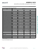
GENERAL DATA ARVU053ZEA2, ARVU063ZEA2, ARVU093ZFA2, ARVU123ZFA2 Table 1: Energy Recovery Ventilation (ERV) Unit General Data Type ERV Units ARVU053ZEA2 ARVU063ZEA2 ARVU093ZFA2 ARVU123ZFA2 470 590 880 1,180 360 470 720 930 14-113 14-113 14-113 14-113 Cross flow fixed core Cross flow fixed core Cross flow fixed core Cross flow fixed core 1 1 1 1 Performance Capacity (CFM) Power Input (SH ) Watts 1 Operating Range Operating Range (°F DB) Air-to-Air Heat Exchanger Quantity Energy Rec
DIMENSIONS MULTI V ERV Engineering Manual ZE Chassis 8 | ERV Due to our policy of continuous product innovation, some specifications may change without notification. LG Electronics U.S.A., Inc..., Englewood Cliffs, NJ. All rights reserved. “LG” is a registered trademark of LG Corp.
DIMENSIONS ZF Chassis Energy Recovery Ventilation (ERV) Units Due to our policy of continuous product innovation, some specifications may change without notification. LG Electronics U.S.A., Inc..., Englewood Cliffs, NJ. All rights reserved. “LG” is a registered trademark of LG Corp.
EFFICIENCY CURVES ARVU053ZEA2 Figure 1: ARVU053ZEA2 Ventilation 1.4 1.2 Super high (ESP = 158) MULTI V ERV Engineering Manual External static pressure [inchAq] 1 0.8 High (ESP = 137) 0.6 Low (ESP = 111) 0.4 0.
EFFICIENCY CURVES ARVU063ZEA2 Figure 2: ARVU063ZEA2 Ventilation 1.4 1.2 (ESP ==165) Super highh(ESP 158) External static pressure [inchAq] Energy Recovery Ventilation (ERV) Units 1 0.8 High (ESP = 148) 0.6 Low (ESP = 120) 0.4 0.
EFFICIENCY CURVES ARVU093ZFA2 Figure 3: ARVU093ZFA2 Ventilation 1.4 1.2 MULTI V ERV Engineering Manual External static pressure [inchAq] 1 Super high (ESP = 158) 0.8 High (ESP = 137) 0.6 Low (ESP = 111) 0.4 0.
EFFICIENCY CURVES ARVU123ZFA2 Figure 4: ARVU123ZFA2 Ventilation 1.4 1.2 External static pressure [inchAq] Energy Recovery Ventilation (ERV) Units Super high (ESP = 165) 1 0.8 High (ESP = 148) 0.6 Low (ESP = 120) 0.4 0.
MULTI V ERV Engineering Manual ELECTRICAL & ACOUSTIC DATA Electrical Data Table 2: ERV Unit Electrical Data Model ARVU053ZEA2 ARVU063ZEA2 ARVU093ZFA2 ARVU123ZFA2 Voltage Range 187-253 Rated Amps (A) 2.8 3.44 5.62 6.
ACOUSTIC DATA Figure 5: ARVU053ZEA2 Figure 6: ARVU063ZEA2 Figure 7: ARVU093ZFA2 Energy Recovery Ventilation (ERV) Units Figure 8: ARVU123ZFA2 Due to our policy of continuous product innovation, some specifications may change without notification. LG Electronics U.S.A., Inc..., Englewood Cliffs, NJ. All rights reserved. “LG” is a registered trademark of LG Corp.
WIRING DIAGRAMS ZE CHASSIS Figure 9: ZE Chassis Wiring Diagram MULTI V ERV Engineering Manual * *Central controller requires PI485 (PSNFP14A0) Note * Purchasea dedicated circuit separately * Field Wiring * Accessory RD : RED BR : BROWN BL : BLUE BK : BLACK OR : ORANGE YL : YELLOW WH : WHITE GN/YL : GREEN / YELLOW • There is risk of electric shock due to failure or electric leakage. • Installation work must be performed by authorized personnel and in accordance with the national wiring standards.
WIRING DIAGRAMS ZF CHASSIS Figure 10: ZF Chassis Wiring Diagram * Energy Recovery Ventilation (ERV) Units *Central controller requires PI485 (PSNFP14A0) Note * Purchasea dedicated circuit separately * Field Wiring * Accessory RD : RED BR : BROWN BL : BLUE BK : BLACK OR : ORANGE YL : YELLOW WH : WHITE GN/YL : GREEN / YELLOW • There is risk of electric shock due to failure or electric leakage.
INSTALLATION & BEST LAYOUT PRACTICES ZE CHASSIS Figure 11: ZE Chassis Installation Drawing Air supply grille (user-supplied) Ceiling suspension bolts position Air return grille (user-supplied) EA (Exaust air outlet) OA MULTI V ERV Engineering Manual Min.
INSTALLATION & BEST LAYOUT PRACTICES ZF CHASSIS Figure 12: ZF Chassis Installation Drawing Air return grille (user-supplied) Air supply grille (user-supplied) Ceiling suspension bolts position A Air return grille (user-supplied) EA D C OA (Fresh air outlet) Min.
INSTALLATION & BEST LAYOUT PRACTICES Main Body Installation • Attach the hanger bracket to the suspension bolt. Use nuts and washers (field supplied) to secure the upper and lower sides of the hanger bracket. • Install the unit after checking the indoor (SA/RA) and outdoor (EA/OA) in accordance with the figure duct direction label. • Install flexible duct between the unit and duct. • Minimum thickness of the insulation for the connecting duct must be 3/8 inch. • Tighten the upper nut.
INSTALLATION & BEST LAYOUT PRACTICES Installing Fixing Bolts • Select and mark the position for the fixing bolts. • Drill a hole on the face of the ceiling for the anchor. Figure 14: Installing Fixing Bolts • Insert the anchor and washer on the suspension bolts to lock them in the ceiling. • Firmly mount the suspension bolts to the anchor. • User nuts, washers and spring washers to secure the installation plates onto the suspension bolt.
MULTI V ERV Engineering Manual INSTALLATION & BEST LAYOUT PRACTICES Connecting Power Wiring Figure 18: Opening Control Box 1. Remove two screws and open the cover of the control box. 2. Connect the main power wires to the terminal block. 3. After inserting the power wires into the bushing, fully insert it into the terminal block for connection. 4. Fix the power wires with the clamp. 5. Pull the power wired to ensure they cannot be removed.
INSTALLATION & BEST LAYOUT PRACTICES • Do not connect wiring of different thickness to the power terminal block (slack in the power wiring could cause abnormal heat). • When connecting wiring which is the same thickness, connect the wiring according to the first image shown below. Figure 21: Connecting Wiring 1. Set the connecting cable into the terminal block of the indoor unit and tighten the screw to lock the conduit bracket to the indoor unit. 2. Join the conduit and the conduit bracket together. 3.
INSTALLATION & BEST LAYOUT PRACTICES Connecting the Duct Figure 25: Connecting the Duct • After securely connecting the duct with the duct connection flange, wrap it with commercial aluminum tape so that air cannot leak out. • Adjust the duct from the ceiling so that no force is applied to the main body of the ventilation system. • Ensure that there are no foreign materials in the duct before connecting the duct. • Ductwork connected to ERV should be insulated to prevent condensation.
INSTALLATION & BEST LAYOUT PRACTICES Table 6: Installer Setting Code and Value Table No.
INSTALLATION & BEST LAYOUT PRACTICES V-Net Wiring • This unit can be used as part of the combined operation system used together with Multi V indoor units or as an independent system for processing outside air. MULTI V ERV Engineering Manual Figure 27: V-Net Wiring - Combined Operation System 26 | ERV Due to our policy of continuous product innovation, some specifications may change without notification. LG Electronics U.S.A., Inc..., Englewood Cliffs, NJ. All rights reserved.
INSTALLATION & BEST LAYOUT PRACTICES Figure 28: V-Net Wiring - Independent System Energy Recovery Ventilation (ERV) Units Due to our policy of continuous product innovation, some specifications may change without notification. LG Electronics U.S.A., Inc..., Englewood Cliffs, NJ. All rights reserved. “LG” is a registered trademark of LG Corp.
MULTI V ERV Engineering Manual MAINTENANCE & SERVICE Maintenance and Service • To prevent the ventilator from deteriorating, clean dust off the air filter and total heat exchanger regularly. Removing the Filter and Heat Exchanger Figure 29: Removing the Filter and Heat Exchanger 1. Remove the maintenance cover. • Place your hands inside of the ceiling from the maintenance cover and pull the maintenance cover up. • Loosen the hinge and detach the maintenance cover. Main Body 2. Remove the air filter.
MAINTENANCE & SERVICE Air Filter Cleaning • Clean the filter once every 6 months. • Clean the dirt from the air filter using a vacuum cleaner or wash it with warm water. • Dry the filter. Do not expose the air filter to direct sunlight or heat from fire. Figure 30: Cleaning the Air Filter Air Filter Energy Recovery Ventilation (ERV) Units Cleaner Air Filter Total Heat Exchanger Cleaning • Use a soft brush and cleanser to remove dirt from the total heat exchanger.
MULTI V ERV Engineering Manual MAINTENANCE & SERVICE Reassembling the Total Heat Exchanger 1. Securely put the corners of the total heat exchanger into the holder for assembly and slide them into the main body. Figure 32: Assembling Total Heat Exchanger and Air Filter Total Heat Exchanger Main Body Assemble the air filter into the holder structure. Holder for Total Heat Exchanger 2. Assemble the air filter into the holding structure inside the total heat exchanger.
MECHANICAL SPECIFICATIONS General ERV indoor units are factory assembled and provided with an internally mounted control circuit board, exhaust fan, supply fan, cross-flow air to air heat exchanger, washable outdoor air and return air filters, and bypass damper. Each unit is designed to operate using 208-230/60/1 power with voltage variances of ±10%. ERV operation range is 14°F - 113°F outdoor temperature.
MULTI V ERV Engineering Manual CONTROLLER GENERAL DATA Zone Controllers and Speciality Application Devices Specifications Table 8: Summary Data—Zone Controllers Zone Controller Name LG Programmable Thermostat Model No. PREMTB010U Case Max Wire Color Length (ft) White Description Allows control of indoor unit on/off, operation mode, occupied and unoccupied temperature setpoints, fan speed, and airflow direction for up to 16 indoor units.
CONTROLLER GENERAL DATA Central Controllers and Integration Solutions Specifications Table 10: Summary Data—Central Controllers (connect to the outdoor unit terminals Internet A, Internet B) Binary Devices Systems Devices No. of Central Signals Name Model No.
LG Electronics Commercial Air Conditioning Division 11405 Old Roswell Road Alpharetta, Georgia 30009 www.lg-vrf.com LG Electronics Commercial Products Support VRF-EM-DT-001-US 014D11 1-888-865-3026 USA Supersedes: VRF-EM-DT-001-US 013L12 Follow the prompts for commercial A/C products.