ENGLISH FRANCAIS ESPAÑOL INSTALLATION MANUAL AIR CONDITIONER • Please read this installation manual completely before installing the product. • Installation work must be performed in accordance with the national wiring standards by authorized personnel only. • Please retain this installation manual for future reference after reading it thoroughly. TYPE : VENTILATOR © LG Electronics U.S.A., Inc., Englewood Cliffs, NJ. All rights reserved. “LG Life’s Good” is a registered trademark of LG Corp. http://www.
ERV Installation Instructions Please read these instructions completely before installing the product. Failure to carefully read and follow all instructions in this manual can result in equipment malfunction, property damage, personal injury and/or death.
Ventilator Installation Manual Installation Requirements Required Parts Required Tools Safety Precaution.................4 Introduction ..........................7 Symbols Used in this manual ..........................7 Feature Dimension Diagram...............................7 Installation ............................9 Installation Map ...................9 • Screws • Screw Driver Installation of Main Body ...11 • Nuts • Spanner Connection of Duct............
Safety Precautions Safety Precautions To prevent injury to the user or other people and property damage, the following instructions must be followed. Incorrect operation due to ignoring instruction will cause harm or damage. The seriousness is classified by the following indications. This symbol indicates the possibility of death or serious injury. This symbol indicates the possibility of injury or damage. Meanings of symbols used in this manual are as shown below. Be sure not to do.
Safety Precautions Do not let the product run for a long time when the humidity is very high and a door or a window is left open. • It may cause injury, accident, or damage to the product. • Moisture may condense and wet or damage furniture. For re-installation of the installed product, always contact the dealer or an Authorized Service Center. Do not open the maintenance cover of the main body during operation.
Safety Precautions Be cautious that water could not enter the product. • If water enters the product, there is risk of fire, electric shock, or product damage. The outside ducts must be tilted at a gradient (1/30 or more) down toward the outdoor area from the ventilator unit, and properly insulated. (The entry of rain water may cause power leaks, fire or damage to household property.) Turn the breaker off when cleaning or maintaining the product.
Introduction ENGLISH Introduction While using the remote controller , refer to attached remote controller manual Symbols used in this Manual This symbol alerts you to the risk of electric shock. This symbol alerts you to hazards that could cause harm to the product. NOTICE This symbol indicates special notes.
Introduction Model : LZ-H150GBA2 [ARVU093ZFA2]/ LZ-H200GBA2 [ARVU123ZFA2] O RA N D SA E B EA OA Maintenance Cover Control Box J L K C G H F M Total Heat Exchanger Air Filter Unit: mm(inch) Model LZ-H150GBA2[ARVU093ZFA2] LZ-H200GBA2[ARVU123ZFA2] Pitch of Suspension Fixture Figure Duct Connection Flange A B C D E F G H J K 1313 (51.7) 1140 (44.9) 738 (29.1) 987 (38.9) 1176 (46.3) 339 (13.3) 242 (9.5) 253 (10) 98 (3.9) 340 (13.4) Weight L 350 (13.
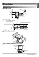
Installation Installation Map (LZ-H080GBA2 [ARVU053ZEA2]/ LZ-H100GBA2 [ARVU063ZEA2]) ■ A PLANE FIGURE RA Grille EA Ventilator SA Grille OA Maintenance Space Inspection Hatch ■ A FRONT VIEW Duct slope: More than 1/30(wall side) Obtaining of Right Distance (Preventing Penetration of Rain Water) Duct Ceiling Fixing Bolt(Supplied by installer) New Type Hood (Preventing Penetration of Rain Water) Ventilator EA OA 1m or more 1m or more Inspection Hatch * 1m = 39.
Installation Installation Map (LZ-H150GBA2 [ARVU093ZFA2]/ LZ-H200GBA2 [ARVU123ZFA2]) ❘■ A PLANE FIGURE RA Grille EA Ventilator OA Maintenance Space Inspection Hatch SA Grille ❘■ A FRONT VIEW Duct slope: More than 1/30(wall side) Obtaining of Right Distance (Preventing Penetration of Rain Water) Ceiling Fixing Bolt(Supplied by installer) New Type Hood (Preventing Penetration of Rain Water) EA OA Inspection Hatch * 1m = 39.
Installation ENGLISH Installation of Main Body Assembly of Washer, Nut Tighten the common washer and nut (more than 21mm (0.83in) for the outside diameter of M10, to the commercial ceiling fixing bolt (M10) as shown in the right figure. Ceiling Fixing Bolt (M10) Nut Spring Washer • For the ceiling fixing bolt, perform work less than 50mm(1.97in) under the ceiling fixing bracket. Washer Nut Connection of Duct 1.
Installation Heat Insulating Material CAUTION: • Check that there are no foreign materials (paper, vinyl, etc) or cutoff powders in the duct before connecting the duct. • Take care so that shock may not be applied to the damper plate within the main body when performing the duct connection work.
Installation 1. Release two screws and then open the cover of the control box. Cover of Control Box Screw • With reference to the below wiring diagram, accurately connect the main power cords into the terminal block. 2. After inserting the power cord into the bushing, fully insert it into the terminal block for connection. • Fix the power cords with the clamp. • Make sure that the power cords may not be removed by pulling them.
Installation ◆ Precautions when laying power wiring Use round pressure terminals for connections to the power terminal block. Round pressure terminal Power wire When none are available, follow the instructions below. • Do not connect wiring of different thicknesses to the power terminal block. (Slack in the power wiring may cause abnormal heat.) • When connecting wiring which is the same thickness, do as shown in the figure below.
Installation ENGLISH Group control 1. When installing more than 2 units of air conditioner to one wired remote controller, please connect as the right figure. • If it is not event communication indoor unit, set the unit as slave. • Check for event communication through the product manual. GND Signal wire 12V GND Signal wire When controlling multiple indoor units with event communication function with one remote controller, you must change the master/slave setting from the indoor unit.
Installation • This unit can be used as part of the combined operation system used together with indoor units(Multi-V system air conditioners), or as an independent system for processing outside air.
How to connect Central Controller(Accessory) C N-OUT C N-C C P I485 Gate Way Main PCB C entral c ontroller 1. Connect between PI485 Gate Way(CN-OUT) and Main PCB(CN-CC). 2. You do not need to set the Option Switch of Main PCB. 3. Please refer to the manual of Accessory for the detail installation method.
In case of finding a problem at a trial operation In case of finding a problem at a trial operation Symptom Counter-measures • Checking the power(rated power 1 phase, 208V/230V, the diameter ø0.6~ø2.0, capacity of breaker) The product doesn’t work though you press the ‘ON’ switch.