ENGLISH LG ITALIANO ESPAÑOL Models: CRNN-SP Series Type: Art Cool FRANÇAIS DEUTSCH • Please read this installation manual completely before installing the product. • Installation work must be performed in accordance with the national wiring standards by authorized personnel only. • Please retain this installation manual for future reference after reading it thoroughly.
Art Cool Type Indoor Unit Installation Manual TABLE OF CONTENTS Installation Requirements Required Parts Required Tools Installation Parts ....................3 Safety Precautions .................4 Installation Selection the best location ....
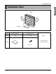
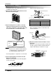
Installation Parts ENGLISH Installation Parts Air Intake Air Outlet Name Installation guide map Quantity 1 EA Securing screws 2 EA (Other) • Owner's manual • Installation manual Shape M4 x 12L Installation Manual 3
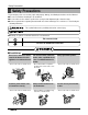
Safety Precautions Safety Precautions To prevent injury to the user or other people and property damage, the following instructions must be followed. ■ Be sure to read before installing the air conditioner. ■ Be sure to observe the cautions specified here as they include important items related to safety. ■ Incorrect operation due to ignoring instruction will cause harm or damage. The seriousness is classified by the following indications. This symbol indicates the possibility of death or serious injury.
Safety Precautions Do not let the air conditioner run for a long time when the humidity is very high and a door or a window is left open. Be cautious when unpacking and installing the product. • There is risk of fire or electric shock. • Moisture may condense and wet or damage furniture. • Sharp edges could cause injury. Be especially careful of the case edges and the fins on the condenser and evaporator. For installation, always contact the dealer or an Authorized Service Center.
Safety Precautions ■ Installation Always check for gas (refrigerant) leakage after installation or repair of product. Install the drain hose to ensure that water is drained away properly. Keep level even when installing the product. • Low refrigerant levels may cause failure of product. • A bad connection may cause water leakage. • To avoid vibration or water leakage. 90˚ Do not install the product where the noise or hot air from the outdoor unit could damage the neighborhoods.
Installation Installation ENGLISH Read completely, then follow step by step. Selection of the best location • Do not have any heat or steam near the unit. • Select a place where there are no obstacles in front of the unit. • Make sure that condensation drainage can be conveniently routed away. Do not install near a doorway. • Ensure that the space around the left and right of the unit is more than 50cm. The unit should be installed as high on the wall as possible, allowing a minimum of 10cm from ceiling.
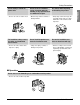
Installation Preparing Work for Installation The wall you select should be strong and solid enough to prevent vibration 1) Open panel front • First pull down the grille bottom, then remove screws(2 pieces), and close grille bottom again. • The moment of lifting the both lower parts of panel front, you can hear sound this panel came out. In this time panel front is separated • After pulling down this panel a bit, separate connecting wire with product.
Installation Sticking the Installation Guide Map and Fixing Indoor Unit 7) Hang the hole of product at the upper screws. (In this time, remove the map) (Falling attention) INSTALLATION GUIDE MAP INS TAL LAT ION GUID EM AP Hanger hole (Rear side of product) 2) Look at suited horizon by horizontal meter on the horizontal setting line, and fix lightly the map by adhesive tape.
Installation Connection of Piping • Preparing the indoor unit's piping and drain hose for installation through the wall. 1) Route the indoor tubing and the drain hose in the direction of rear left or right. • Tighten the flare nut with a wrench. Open-end wrench (fixed) Flare nut Connection pipe Wrench Indoor unit tubing Pipe Size[Torque] Drain hose 2) Tape the tubing, drain hose, and the connecting cable. Be sure that the drain hose is located at the lowest side of the bundle.
Installation • Wrap the area which accommodates the rear piping housing section with vinyl tape. Indoor unit pipe Connection pipe Vinyl tape (wide) Wrap with vinyl tape Wrap with vinyl tape Pipe Connecting cable Vinyl tape(wide) Drain hose Pipe Vinyl tape(narrow) Drain Piping 1) To check the drainage. • Pour a glass of water on the evaporator. • Ensure the water flows through the drain hose of the indoor unit without any leakage and goes out the drain exit.
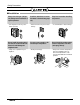
Installation Front Panel Assembly 1) First, check the side cover assembly exactly. 2) Assemble connecting lead wire with control and first fix the upper part of panel front, then match the lower part of panel front Panel Front Connector 3) Drive two screws.
Installation Wiring Connection Terminal Block in Outdoor Terminal Block Indoor 1(L) 2(N) 3 4 C D Vcc A B • When installing, refer to the circuit diagram on the Control Box of Indoor Unit. • When installing, refer to the wiring diagram on the Control Cover Inside Outdoor Unit. INDOOR POWER INPUT CAUTION • The above circuit diagram is subject to change without notice. • Be sure to connect wires according to the wiring diagram. • Connect the wires firmly, so that not to be pulled out easily.
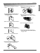
Installation Installation of Remote Controller HOW TO MOUNT ONTO A WALL HOW TO INSERT BATTERIES 1. Remove the battery cover from the remote controller. • Slide the cover according to the arrow direction. 2. Insert the two batteries. • Be sure that the (+) and (-) directions are correct. • Be sure that both batteries are new. 3. Re-attach the cover. • Slide it back into position.