
Installation guide


Installation Manual 13
ENGLISH
Installation
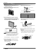
Circuit Breaker
Use a circuit
breaker or time
delay fuse.
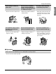
• Connect the cable to the indoor unit by connecting the wires to the terminals on the control board in-
dividually according to the outdoor unit connection. (Ensure that the color of the wires of the outdoor unit
and the terminal No. are the same as those of the indoor unit.)
The earth wire should be longer than the common wires.
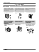
• When installing, refer to the circuit diagram
on the Control Box of Indoor Unit.
• When installing, refer to the wiring diagram
on the Control Cover Inside Outdoor Unit.
Terminal Block Indoor
1(L) 2(N) 3 4
INDOOR POWER INPUT
Terminal Block in Outdoor
ABC D Vcc
Air
Conditioner
Main power source
CAUTION
• The above circuit diagram is subject to change without notice.
• Be sure to connect wires according to the wiring diagram.
• Connect the wires firmly, so that not to be pulled out easily.
• Connect the wires according to color codes by referring the wiring diagram.
CAUTION After the confirmation of the above conditions,
prepare the wiring as follows:
1) Never fail to have an individual power circuit specifically for the air conditioner. As for the method of
wiring, be guided by the circuit diagram posted on the inside of control cover.
2) The screws which fasten the wiring in the casing of electrical fittings are liable to come loose from vibra-
tions to which the unit is subjected during the course of transportation. Check them and make sure that
they are all tightly fastened. (If they are loose, it could cause burn-out of the wires.)
3) Specification of power source.
4) Confirm that electrical capacity is sufficient.
5) See to that the starting voltage is maintained at more than 90 percent of the rated voltage marked on the
name plate.
6) Confirm that the cable thickness is as specified in the power source specification.
(Particularly note the relation between cable length and thickness.)
7) Always install an earth leakage circuit breaker where it is wet or moist.
8) The following would be caused by voltage drop.
• Vibration of a magnetic switch, which will damage the contact point, fuse breaking, disturbance of the normal
function of the overload protection device.
9) The means for disconnection from a power
supply shall be incorporated in the fixed wiring and have an air gap contact separation of at least 3mm in
each active(phase) conductors.
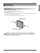
CAUTION If a power plug is not to be used,
provide a circuit breaker between power
source and the unit as shown below.
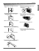
Wiring Connection