website http://www.lgservice.com e-mail http://www.lgeservice.com/techsup.html LG System Heat Pump Indoor Unit INSTALLATION MANUAL MODELS: CRNN-BN/BJ Series Type: Ceiling Concealed Duct - Low Static IMPORTANT • Please read this installation manual completely before installing the product. • Installation work must be performed in accordance with the national wiring standards by authorized personnel only. • Please retain this installation manual for future reference after reading it thoroughly.
Ceiling Concealed Duct - Low Static Type Indoor Unit Installation Manual TABLE OF CONTENTS Installation Requirements Required Parts Required Tools Installation Parts Provided....3 Safety Precautions .................4 Installation Selection the best location ....7 Ceiling opening dimension and hanging bolt location ......8 Wiring Connection .................
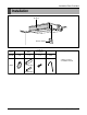
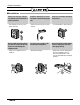
Installation Parts Provided Installation Air filters Remote Control Name Clamp metal Insulation for fitting Screws for duct flanges Clamp Quantity 1 EA 1 set 1 set 8 EA (Other) • Owner's manual • Installation manual Shape for gas pipe for liquid pipe Installation Manual 3
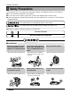
Safety Precautions Safety Precautions To prevent injury to the user or other people and property damage, the following instructions must be followed. ■ Be sure to read before installing the air conditioner. ■ Be sure to observe the cautions specified here as they include important items related to safety. ■ Incorrect operation due to ignoring instruction will cause harm or damage. The seriousness is classified by the following indications. This symbol indicates the possibility of death or serious injury.
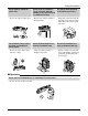
Safety Precautions Do not modify or extend the power cable. Do not let the air conditioner run for a long time when the humidity is very high and a door or a window is left open. Be cautious when unpacking and installing the product. • There is risk of fire or electric shock. • Moisture may condense and wet or damage furniture. • Sharp edges could cause injury. Be especially careful of the case edges and the fins on the condenser and evaporator.
Safety Precautions ■ Installation Always check for gas (refrigerant) leakage after installation or repair of product. Install the drain hose to ensure that water is drained away properly. Keep level even when installing the product. • Low refrigerant levels may cause failure of product. • A bad connection may cause water leakage. • To avoid vibration or water leakage. 90˚ Do not install the product where the noise or hot air from the outdoor unit could damage the neighborhoods.
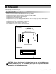
Installation Installation Read completely, then follow step by step. Selection of the best location Install the air conditioner in the location that satisfies the following conditions. • The place shall easily bear a load exceeding four times the indoor unit’s weight. • The place shall be able to inspect the unit as the figure. • The place where the unit shall be leveled. • The place shall allow easy water drainage.(Suitable dimension “H” is necessary to get a slope to drain as figure.
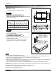
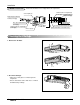
Installation Ceiling dimension and hanging bolt location ■ Installation of Unit Install the unit above the ceiling correctly. D B CASE 1 C E POSITION OF SUSPENSION BOLT • Apply a joint-canvas between the unit and duct to absorb unnecessary vibration. F (Unit:mm) Dimension A C D E F G H I 2.1(7,165) 783 667 300 100 500 20 639 120 220 2.6(8,871) 873 767 300 100 500 20 729 120 220 3.
Installation • Select and mark the position for fixing bolts. • Drill the hole for set anchor on the face of ceiling. • Insert the set anchor and washer onto the suspension bolts for locking the suspension bolts on the ceiling. • Mount the suspension bolts to the set anchor firmly. • Secure the installation plates onto the suspension bolts (adjust level roughly) using nuts, washers and spring washers.
Installation THERMAL INSULATION All thermal insulation must comply with local requirement. Union for liquid pipe Refrigerant pipe and thermal insulator(Local supply) Hose crip for thermal insulator (Local supply) Thermal insulator for refrigerant pipe (Local supply) Union for gas pipe Checking the Drainage 1. Remove the Air Filter. 2. Check the drainage. • Spray one or two glasses of water upon the evaporator. • Ensure that water flows drain hose of indoor unit without any leakage.
Installation CAUTION 1. Install declination of the indoor unit is very important for the drain of the duct type air conditioner. 2. Minimum thickness of the insulation for the connecting pipe shall be 5mm. Front of view • The unit must be horizontal or declined to the drain hose connected when finished installation. 1~3mm Ceiling Drainage hole CORRECT Drainage hole INCORRECT CAUTION FOR GRADIENT OF UNIT AND DRAIN PIPING • Possible drain-head height is up to 700mm.
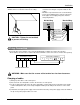
Installation CAUTION: After the confirmation of the above conditions, prepare the wiring as follows: 1) Never fail to have an individual power specialized for the air conditioner. As for the method of wiring, be guided by the circuit diagram pasted on the inside of control box cover. 2) Provide a circuit breaker switch between power source and the unit.
Installation Installation of Remote Control • Although the room themperature sensor is in the indoor unit, the remote control should be installed in such places away from direct sunlight and high humidity. Installation of the remote control • Select places that are not splashed with water. • Select control position after receiving customer approval. • The room temperature sensor is built in the indoor unit. • This remote control equipped with liquid crystal display.
Installation Drain Pipe Work 1) Drain pipe gradient and support a) - The drain pipe must be fitted at a gradient of at least 1/100. - The drain pipe should be as short as possible and free from airlocks.
Installation 3) Ground drain piping a) It is standard work practice to make connections to the main pipe from above. The pipe down from the combination should be as large as possible. Face the vent pipe mouth downward to keep foreign matter from penetrating the system Face piping downward Vent pipe b) The pipe work should be kept as short as possible and he number of indoor units per group kept to a minimum.
Installation Installation of drain pump 1) Safety First • Cut off the power supply before installation and maintenance. • Drain Pump Assy, Elbow and Hose must be installed at safe area where it is far away from the user. • Drain Pump Assy must be installed at appointed location. • All wiring and connections are for installation only.
Installation 5) Attention 1. Possible drain-head height is up to 700mm. So, it must be installed below 700mm. 1/50~1/100 1/50~1/100 2. Keep the drain hose downward up to 1/50~1/100 inclination. Prevent any upward flow or reverse flow in any part. 1/50~1/100 Drain Pipe MAX 700mm Drain Pump 3. 5mm or thicker formed thermal insulator is provided for the drain pipe. Thermal insulator (Local supply) Drain pipe (Local supply) Unit Elbow Drain pump 4. Upward routing is not allowed. 5.
Installation Optional operation 1) Two Thermistor System Room Temp. sensor Slide switch for 2 Thermistor TH R13H OP2 R14H OP3 REMO MAIN 2TH REMO MAIN 2TH CO1H OP5R16H OP4 R15H OP1 R19H R11H SW TH Position 2 Position 1 Position 3 R12H OP7 R18H R17H OP6 LO C070 STAND R03S HI R04S SW R01S R02S (1) Open the rear cover of the wired remote-control to set the mode. (2) Select one of three selectable modes as follows.
P/No.: 3828A20326A Printed in Korea After reading this manual, keep it in a place easily accessible to the user for future reference.