website:http://biz.LGservice.com e-mail:http://www.LGEservice.com/techsup.html COLOR TV SERVICE MANUAL CHASSIS : MC-022A MODEL:RT-29FB50RB/RE/RP/RX MODEL:RT-29FB50VB/VE CAUTION BEFORE SERVICING THE CHASSIS, READ THE SAFETY PRECAUTIONS IN THIS MANUAL. P/NO : 3828VD0118Z Feb.
CONTENTS Contents ................................................................................................................. 2 Safety Precautions ............................................................................................3 Specifications ..................................................................................................... 4 Control Descriptions ........................................................................................ 5 Disassembly Instructions ........
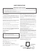
SAFETY PRECAUTIONS IMPORTANT SAFETY NOTICE Many electrical and mechanical parts in this chassis have special safety-related characteristics. These parts are identified by in the Schematic Diagram and Replacement Parts List. It is essential that these special safety parts should be replaced with the same components as recommended in this manual to prevent X-RADIATION, Shock, Fire, or other Hazards. Do not modify the original design without permission of manufacturer.
SPECIFICATIONS Note : Specification and others are subject to change without notice for improvement. O O O Video input system: PAL-B/G, D/K, I/I SECAM-B/G, D/K/L/L’ NTSC M NTSC 4.43(AV) NTSC- M/PAL M-N SOUND IF : Intermediate Frequency (Unit : MHz) VISION IF : 38.9MHz,33.9MHz(SECAM-L’) COLOR IF : 34.47MHz(4.43) 35.32MHz(3.58) : NTSC-M VIF-4.25000MHz ( ): SECAM VIF-4.40625MHz 33.4MHz (B/G) 32.9MHz (I/I) 32.4MHz (D/K,L) 34.4MHz (M) 40.
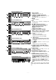
DESCRIPTION OF CONTROLS All the functions can be controlled with the remote control handset. Some functions can also be adjusted with the buttons on the front panel of the set. POWER MUTE 11 1 Before you use the remote control handset, please install the batteries. See the next page. 1 2 3 4 5 6 7 8 9 ARC 0 TV/AV 2 1. POWER switches the set on from standby or off to standby. 12 3 SOUND MENU PICTURE 4 ( ) PR 5 VOL VOL 2.
14. OK accepts your selection or displays the current mode. 15. LIST displays the programme table. POWER MUTE 11 1 16. EYE/ (option) switches the eye function on or off. * 17. SLEEP sets the sleep timer. 2 18. Q.VIEW returns to the previously viewed programme. selects a favorite programme. 3 1 2 3 4 5 6 7 8 9 ARC 0 TV/AV PICTURE MENU 12 SOUND 4 13 OK T U R B O 19. PIP BUTTONS (option) PIP switches the sub picture on or off. PR +/selects a programme for the sub picture.
RF/RT-25/29CA40 series MENU OK VOL 1. MAIN POWER switches the set on or off. PR ON/OFF 12 S-VIDEO VIDEO 13 L/MONO AUDIO R AV3 1 34 2 6 11 5 3. MENU selects a menu. CF/CT-25/29M30 series 4. OK accepts your selection or displays the current mode. TV/AV ON/OFF VOL 12 1 2 6 PR 7 8 5. D / E (Programme Up/Down) selects a programme or a menu item. switches the set on from standby. F / G (Volume Down/Up) adjusts the volume. adjusts menu settings.
DISASSEMBLY INSTRUCTIONS Important note Chassis Assy Removal This set is disconnected from the power supply through the converter transformer. An isolating transformer is necessary for service operations on the primary side of the converter transformer. Grasp both side of Frame and pull it backward smoothly. Back Cabinet Removal Remove the screws residing on the back cabinet and carefully separate the back cabinet from the front cabinet. (Fig. 2-1). CPT Removal PICTURE TUBE HANDLING CAUTION 1.
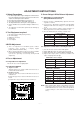
ADJUSTMENT INSTRUCTIONS 1. Safety Precautions 5. Screen Voltage & White Balance Adjustment 1. It is safe to adjust after using insulating transformer between the power supply line and chassis input to prevent the risk of electric shock and protect the instrument. 2. Never disconnect leads while the TV receiver is on. 3. Don't short any portion of circuits while power is on. 4. The adjustment must be done by the correct appliances. 5. Unless otherwise noted, set the line voltage to 230Vac!10%, 50Hz. 6.
6. Deflection Data Adjustment (Line SVC-2) NOTE : How to enter into the Line Service Mode with a remocon. EW (Horizontal Width) Adjust to that a digital circle pattern looks like exact circle. 1.Power off. 2.Press the Red button. 3.Press the Green button. 4.Press the Yellow button. 5.Press the Cyan button. 6.Press the OK button. 7.Power On. 6-1. Preparation for Deflection Adjustment 1) At adjustment mode(IN-START button on remote control of adjustment),changed to LINE SVC 2 mode to adjust the deflection.
25/29” LG FLAT CPT(CT-25Q20RB) 29” S/S SEB FLAT CPT ITEM RANGE N50Hz W50Hz Z50Hz ITEM RANGE N50Hz W50Hz Z50Hz VA 0050~00CF 009A 22 11 VA 0050~00CF 00A3 -22 11 VL 0025~00BF 00F3 3 0 VL 0025~00BF 00F5 0 0 SC 0000~009F 00D0 0 0 SC 0000~009F 00D0 0 0 VS 0600~0900 0774 0 0 VS 0600~0900 0744 0 0 HS 0000~003F 0019 0 0 HS 0000~003F 0016 0 0 EW 0400~0EFF 0B96 22 0 EW 0400~0EFF 0E40 0 0 ET 0700~08FF 07DE 0 0 ET 0700~08FF 07E9 0 0 EP 06
16: 9 ITEM 14: 9 ZOOM STANDARD RANGE 50Hz 60Hz 50Hz 60Hz 50Hz 60Hz 50Hz 60Hz VA 0050~00CF 0083 0083 008F 008E 00A7 00A7 0083 0084 VL 0025~00BF 00FD 00FA 00FD 00A 00FD 00F8 00FD 00F9 7. SVC Data & PSM,SSM Data.
8-3. OPTION 1 Function Option WIDE TOP ACMS CH+AU EYE DEG TILT KEY Code 8-5.
8-7. OPTION 4 Function OPTION FUNTION CODE 0 English Only(Eng.) Arab.Asia 1 Arab(Eng/Fr/Arab) 3834 2 Urdu(Eng/Fr/Arab/Urdu) 3 Asia(Eng/Fr/Indonesia) 0 English Only(Eng.) Farsi 1 Arab(Eng/Fr/Arab) 3834 2 Farsi(Eng/Fr/Arab/Farsi) OSD 0 English Only(Eng.) Arab-Asia LANG. 1 Arab(Eng/Fr/Arab) 3804 2 Urdu(Eng/Fr/Arab/Urdu) 3 Arab all(Eng/Fr/Arab/Urdu/Farsi) 4 Farsi ONly(Eng/Farsi) 5 Asia(Eng/Fr/Indonesia/Malay) 0 English Only(Eng.) WEST-EU 1 EU-7(E.
OPTION TXT-L FUNTION CODE 0 WEST-EU Farsi only 1 EAST-EU 3834 only(W/TXT) 2 Turkey 3 Cyrillic3 5 Arab/English 8 Farsi/English 0 WEST-EU Arab-Asia 1 EAST-EU 3834 only(W/TXT) 2 Turkey 3 Cyrillic3 5 Arab/English 0 WEST-EU WEST EU 1 EAST-EU 3834 only(W/TXT) 2 Turkey 6 Cyrillic3 0 WEST-EU EAST EU 1 EAST-EU 3834 only(W/TXT) 2 Turkey 6 Cyrillic3 0 WEST-EU 28” WIDE FLAT 1 EAST-EU 3834 only(W/TXT) 2 Turkey 4 Cyrillic3 5 Arab/English 6 Farsi/English - 15
- 16 - ICP101 Y&C AV -3 AV -2 AV -1 PIP &A/V SW ICP01 IC661 MSP-34xxG L/R RGB & FB SCART-1 RGB & FB SDASDA9489X PIP Processor V- SYNC H- SYNC I 2C Bus Ik DVD Y, Pb,Pr 8 H-Sinc H-Out ST-2310 IC03 AT24C16 EEPROM LA-7845 Tilt Control Vetical Deflection IC301 Tilt Controller VA V-Out T402 H-Out R G B AMP (6107)JF TDA 6109 TO TILT COIL V-DY FBT VMVM-COIL H -DY TO Cathode 0f CPT MAIN SPEAKER L R IC901 Horizontal Deflection IC401 EW VM R/G/B TDA-2066 (Mono Opt.
- 17 - 12 110V(Flat) 120V (Normal) 18 33V 16 17V 14 Sound Vcc (35V OPT.) 8V T802 12V 11 SMPS TRANS ST-BY TRANS 28V(FBT) Relay 9V ST 5V Tilt(Opt.) 5V FBT H-DRIVE 5V EW AMP 278R05 LD3.3V LA 7845(V-AMP) KA78A09 12V 78L05 ¡ 14V(FBT) T803 VM Tuner (Main) IC01 VCT3834 LD3.3V 7805 12V 200V(FBT) Tuner (Sub) EYE(Opt.
TROUBLE SHOOTING RF- STEREO Selected correct system In menu OK NO Check the waveform At pin 17 of TU101 Check / Replace TU 101 OK NO Check the waveform At pin 24,25 of IC661 Check The Voltage At pin 16,33,46, of IC661 NO Check The voltage At pin of IC610, IC853 OK NO Check the waveform At pin 4,12 of IC602 NO Check / Replace Q671, 672 NO Check / Replace Q621, IC603 NO Check / Replace F851, D862 Check / Replace IC610, IC853 OK Check the Voltage At pin 6, 7 of IC602 OK Check the waveform
NO RASTER CHECK B+ At D807 cathode Normal Abnormal Is the voltage at Pin 25, 54 of IC01 3.
No Picture / No Sound Is any OSD displayed? OK No OK Check receiving system in MENU & execute Auto - Program. Check IC01 pin37,42,43,44 (IK, R,G,B) No OK Does the auto - Program Operate properly. OK Check / Replace IC01 Store on manual - program MENU Check 5V, 33V & IIC Bus Line No Check 5V, 33V & IIC Bus Line Of Tuner. OK Check / Replace IC01, Tuner No Is the CVBS signal OK.
AV Stereo Select correct system In menu OK OK Check the connection Of AV equipment AV NO Check the the waveform At pin47 of IC661 OK Check TU101 Tuner OK NO Check the waveform At pin 24, 25, of IC661 Check the voltage Of pin16,20 OK NO Check waveform At pin 4, 12 of IC602 Check / Replace IC602 OK NO Check the voltage At pin6,7 of IC602 Check / Replace Q621, IC603 OK Check the waveform At pin 1,2,14,15 of IC602 NO Check the vpltage At pin3, 13 of IC602 OK Replace IC 602 - 21 - NO Chec
EXPLODED VIEW 913 943 170 400 150 510 112 174 120 121 530 520 300 104 310 700 330 320 - 22 -
The components identified by mark critical for safety. Replace only with part number specified. EXPLODED VIEW PARTS LIST LOCA.
REPLACEMENT PARTS LIST LOCA. NO PART NO DESCRIPTION LOCA. NO IC PART NO DESCRIPTION “ 0DR100009FA DIODE,RECTIFIERS EU1DGR TP D803 0DD100009AM DIODE,RECTIFIERS EU1ZV(1) TP SANKEN HIC920 0IZZVF0018A STK396-110 11P ST SCAN VELOCITY MODU.
For Capacitor & Resistors, the charactors at 2nd and 3rd digit in the P/No. means as follows; LOCA. NO CC, CX, CK, CN : Ceramic CQ : Polyestor CE : Electrolytic PART NO RD : Carbon Film RS : Metal Oxide Film RN : Metal Film RF : Fusible DESCRIPTION LOCA. NO PART NO DESCRIPTION Q183 0TR534309AA TR,2SC5343Y TP AUK - - C120 0CN1030F679 10000P 16V M Y TA52 Q184 0TR534309AA TR,2SC5343Y TP AUK - - C121 0CE474DK618 0.
For Capacitor & Resistors, the charactors at 2nd and 3rd digit in the P/No. means as follows; LOCA. NO PART NO DESCRIPTION PART NO RD : Carbon Film RS : Metal Oxide Film RN : Metal Film RF : Fusible DESCRIPTION C311 0CQ1031N509 0.01U 100V K POLY 181-007F ECQ-V1H224JL3,50V C401 0CE474DK618 0.4700UF STD 50V M FL TP5 C650 0CN1030F679 10000P 16V M Y TA52 C401 0CE105DK618 1UF STD 50V M FL TP5 C651 0CN1030F679 10000P 16V M Y TA52 C402 0CE475DK618 4.
For Capacitor & Resistors, the charactors at 2nd and 3rd digit in the P/No. means as follows; LOCA. NO CC, CX, CK, CN : Ceramic CQ : Polyestor CE : Electrolytic PART NO RD : Carbon Film RS : Metal Oxide Film RN : Metal Film RF : Fusible DESCRIPTION LOCA. NO PART NO DESCRIPTION C860 0CE108BF618 1000UF KME 16V M FL TP5 J225 0LA0391K119 INDUCTOR,AXIAL LEAD 3.9UH K 2.3*3.4 TP C861 0CE108DF618 1000UF STD 16V M FL TP5 J347 0LA0391K119 INDUCTOR,AXIAL LEAD 3.9UH K 2.3*3.
For Capacitor & Resistors, the charactors at 2nd and 3rd digit in the P/No. means as follows; LOCA. NO PART NO DESCRIPTION LOCA. NO PART NO CC, CX, CK, CN : Ceramic CQ : Polyestor CE : Electrolytic DESCRIPTION P802B 366-009D CONNECTOR,2.36PAI 1P . K/M AUTO R128 0RD0222F609 22 OHM 1/6 W 5.00% TA52 P901 366-009D CONNECTOR,2.36PAI 1P . K/M AUTO R129 0RD1000F609 100 OHM 1/6 W 5% TA52 P903 366-009D CONNECTOR,2.36PAI 1P .
For Capacitor & Resistors, the charactors at 2nd and 3rd digit in the P/No. means as follows; LOCA. NO CC, CX, CK, CN : Ceramic CQ : Polyestor CE : Electrolytic PART NO RD : Carbon Film RS : Metal Oxide Film RN : Metal Film RF : Fusible DESCRIPTION LOCA. NO PART NO DESCRIPTION R313 0RS3900J607 390 OHM 1 W 5.00% TA62 R537 0RD2202F609 22K OHM 1/6 W 5% TA52 R315 0RD1000F609 100 OHM 1/6 W 5% TA52 R541 0RD2700F609 270 OHM 1/6 W 5% TA52 R316 0RD2702F609 27K OHM 1/6 W 5.
For Capacitor & Resistors, the charactors at 2nd and 3rd digit in the P/No. means as follows; LOCA. NO PART NO DESCRIPTION LOCA. NO CC, CX, CK, CN : Ceramic CQ : Polyestor CE : Electrolytic PART NO RD : Carbon Film RS : Metal Oxide Film RN : Metal Film RF : Fusible DESCRIPTION R833 0RP0050H709 0.05 OHM 1/2 W 10% TA52 R850 0RD0471F609 4.7 OHM 1/6 W 5% TA52 R852 0RS0102K619 10 OHM 2 W 5% TR SW01 140-315A SWITCH,TACT SKHV17910B LG C&D NON 12V R858 0RD0471F609 4.
P/NO:3854VA0098A-S(1/2) 2002.03.
PRINTED CIRCUIT BOARD MAIN CONTROL P/N: 3854VA0098A-S(2/2) DATE: 2002.03.25 COMPONENT LOCATION GUIDE C01 ..........B4 C02 ..........B4 C03 ..........B4 C04 ..........B4 C06 ..........E1 C07 ..........B4 C08 ..........B4 C10 ..........B3 C11 ..........B3 C14 ..........B4 C16 ..........B4 C17 ..........B4 C22 ..........B4 C23 ..........C4 C24 ..........C4 C25 ..........C4 C27 ..........B4 C28 ..........C4 C29 ..........B4 C30 ..........C1 C102 ........A5 C103 ........A5 C104 ........A5 C105 ........
SVC. SHEET : 3854VA0098A-S SVC.