
Owner's Manual English, Spanish 07/18/2017 14296K
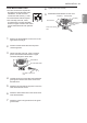
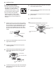
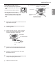
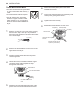
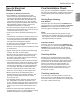
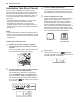
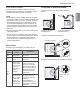
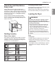
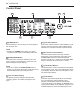
Table Of Contents
- PRODUCT FEATURES
- SAFETY INSTRUCTIONS
- PRODUCT OVERVIEW
- INSTALLATION
- Installation Overview
- Product Specifications
- Installation Location Requirements
- Clearances
- Leveling the Dryer
- Reversing the Door
- Installing the Side Vent Kit
- Venting the Dryer
- Connecting Gas Dryers
- Connecting Electric Dryers
- Special Electrical Requirements
- Final Installation Check
- Installation Test (Duct Check)
- OPERATION
- SMART FUNCTIONS
- MAINTENANCE
- TROUBLESHOOTING
- WARRANTY
- CARACTERÍSTICAS DEL PRODUCTO
- INSTRUCCIONES DE SEGURIDAD
- DESCRIPCIÓN GENERAL DEL PRODUCTO
- INSTALACIÓN
- Descripción general de la instalación
- Especificaciones del producto
- Requisitos del lugar de instalación
- Espacios libres
- Nivelación de la secadora
- Inversión de la puerta
- Instalación del kit de ventilación lateral
- Ventilación de la secadora
- Conexión de secadoras de gas
- Conexión de secadoras eléctricas
- Requisitos eléctricos especiales
- Revisión final de la instalación
- Prueba de instalación (Revisión de conductos)
- FUNCIONAMIENTO
- FUNCIONES INTELIGENTES
- MANTENIMIENTO
- SOLUCIÓN DE PROBLEMAS
- GARANTÍA

23INSTALLATION
ENGLISH
Four-Wire Direct Wire
• A 4-wire connection is required for
all mobile and manufactured home
installations, as well as all new
construction after January 1, 1996.
• A UL-listed strain relief is required.
• Use UL-listed 4-wire #10 AWG-
minimum copper conductor cable.
Allow at least 5 ft. (1.5 m) of wire to
allow for removal and reinstallation of
the dryer.
1
Remove 5-inch (12.7 cm) of the outer covering
from the wire. Remove 5-inch of insulation from
the ground wire. Cut off approximately 1.5-inch
(3.8 cm) from the other three wires and strip 1
inch (2.5 cm) insulation from each wire. Bend
the ends of the three shorter wires into a hook
shape.
1" (2.5 cm)
Ground Wire
5" (12.7 cm)
2
Remove the terminal block access cover on the
upper back of the dryer.
3
Install a UL-listed strain relief into the power
cord through-hole.
4
Thread the 4-wire #10 AWG-minimum copper
power cable prepared in step 1 through the
strain relief.
Terminal Block
UL-Listed Strain Relief
UL-Listed 4-Wire Power
Cord
5
Transfer the dryer’s ground wire from behind the
green ground screw to the center screw of the
terminal block.
6
Attach the two hot leads of the power cord to the
outer terminal block screws.
7
Attach the white neutral wire to the center screw
of the terminal block.
8
Attach the power cord ground wire to the green
ground screw.
9
Tighten all screws securely.
10
Reinstall the terminal block access cover.
Hot (Black)
Ground Screw
Power Cord Ground
Wire
White Wire moved from
Ground Screw
Hot (Red)
Neutral (White)
Three-Wire Power Cord
• A 3-wire connection is NOT permitted
on new construction after January 1,
1996.
• A UL-listed strain relief is required.
• Use a 30-amp, 240-volt, 3-wire,
UL-listed power cord with #10 AWG-
minimum copper conductor and closed
loop or forked terminals with upturned
ends.
1
Remove the terminal block access cover on the
upper back of the dryer.
2
Install a UL-listed strain relief into the power
cord through-hole.
3
Thread a 30-amp, 240-volt, 3-wire, UL-listed
power cord with #10 AWG-minimum copper
conductor through the strain relief.
Terminal Block
UL-Listed Strain Relief
UL-Listed 3-Wire Power
Cord
4
Attach the two hot leads (black and red) of the
power cord to the outer terminal block screws.
5
Attach the neutral (white) wire to the center
terminal block screw.
6
Connect the external ground (if required by local
codes) to the green ground screw.
7
Tighten all screws securely.
8
Reinstall the terminal block access cover.
Hot (Black)
Ground Screw
White Wire from Dryer
harness
External Ground Wire (If
required by local codes)
Hot (Red)
Neutral (White)