OWNER'S MANUAL DRYER Read this owner’s manual thoroughly before operating the appliance and keep it handy for reference at all times. ENGLISH ESPAÑOL DLE3500*, DLG3501* DLE3460*, DLG3461* DLEX3700*, DLGX3701* DLEX3900*, DLGX3901* MFL67652521 Rev.10_022820 www.lg.com Copyright © 2018 - 2020 LG Electronics Inc. All Rights Reserved.
TABLE OF CONTENTS 3 PRODUCT FEATURES 45 SMART FUNCTIONS 45 48 LG ThinQ Application Smart Diagnosis™ Function 4 SAFETY INSTRUCTIONS 5 IMPORTANT SAFETY INSTRUCTIONS 49 MAINTENANCE 9 PRODUCT OVERVIEW 49 9 9 Parts Accessories 50 TROUBLESHOOTING 10 INSTALLATION 10 10 11 12 14 15 16 17 18 20 21 23 28 28 29 Installation Overview Product Specifications Installation Location Requirements Clearances Leveling the Dryer Reversing the Door Installing the Side Vent Kit Stacking the Dryer Venting the
PRODUCT FEATURES 3 PRODUCT FEATURES Rotate the cycle selector knob to select the desired dry cycle. Add cycle options or adjust settings with the touch of a button. Easy-Access Reversible Door The wide-opening door provides easy access for loading and unloading. The door hinge can be reversed to adjust for installation location. Steam Functions (Steam Models) LG’s steam technology allows you to inject fabrics with a swirling jet of hot steam to refresh clothes, reduce static, and make ironing easier.
SAFETY INSTRUCTIONS SAFETY INSTRUCTIONS READ ALL INSTRUCTIONS BEFORE USE Your safety and the safety of others are very important. We have provided many important safety messages in this manual and on your appliance. Always read and follow all safety messages. This is the safety alert symbol. This symbol alerts you to potential hazards that can kill or injure you and others. All safety messages will follow the safety alert symbol and either the word WARNING or CAUTION.
SAFETY INSTRUCTIONS 5 IMPORTANT SAFETY INSTRUCTIONS WARNING INSTALLATION ••Before use, the appliance must be properly installed as described in this manual. ••Connect to a properly rated, protected, and sized power circuit to avoid electrical overload. ••To reduce the risk of severe injury or death, follow all installation instructions. ••The appliance must be installed and electrically grounded by qualified service personnel in accordance with local codes.
SAFETY INSTRUCTIONS ••Place the dryer at least 18 inches above the floor for a garage installation. ••Do not use sheet metal screws or other fasteners which extend into the duct that could catch lint and reduce the efficiency of the exhaust system. Secure all joints with duct tape. ••Use only rigid, semi-rigid or flexible metal 4-inch diameter duct inside the dryer cabinet or for exhausting to the outside. Use of plastic or other combustible ductwork may cause a fire.
SAFETY INSTRUCTIONS 7 ••Read all instructions before using the appliance and save these instructions. ••Use this appliance only for its intended purpose. ••Do not allow children to play on, in or with the appliance. Close supervision of children is necessary when the appliance is used near children. ••Do not tamper with controls. ••In the event of a gas leak (propane gas, LP gas, etc.) do not operate this or any other appliance. Open a window or door to ventilate the area immediately.
SAFETY INSTRUCTIONS MAINTENANCE ••Do not repair or replace any part of the appliance. All repairs and servicing must be performed by qualified service personnel unless specifically recommended in this Owner’s Manual. Use only authorized factory parts. ••Do not disassemble or repair the appliance by yourself. ••Remove any dust or foreign matter from the power plug pins. ••Disconnect this appliance from the power supply before cleaning and attempting any user maintenance.
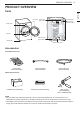
PRODUCT OVERVIEW 9 PRODUCT OVERVIEW Reversible door ENGLISH Parts Power Cord (gas models) Terminal Block Access Panel (electric models) Control panel Lint filter Leveling feet Gas connection (gas models) Exhaust Duct Outlet Accessories Included Accessories Drying Rack (on some models) Inlet Hose-Short (Steam Models) Inlet Hose-Long (Steam Models) Optional Accessories Pedestal (sold separately) Stacking kit (sold separately) Side vent kit (sold separately) Kit No.
INSTALLATION INSTALLATION Installation Overview Please read the following installation instructions first after purchasing this product or transporting it to another location.
INSTALLATION 11 Installation Location Requirements WARNING The installation requires: ••A location that allows for proper exhaust installation. A gas dryer must be exhausted to the outdoors. See Venting the Dryer. ••A grounded electrical outlet located within 2 ft. (61 cm) of either side of the dryer. See Connecting Electric Dryers. ••A sturdy floor to support the total dryer weight of 200 lb (90.7 kg). The combined weight of a companion appliance should also be considered.
INSTALLATION Clearances 14" max.* (356 mm) 14" max.* (356 mm) 18" min.* (457 mm) 18" min.* (457 mm) 1"* 30.2" 5"** (25 mm) (765mm) (127 mm) 1"* 30.2" 5"** (25 mm) (765mm) (127 mm) 3"* (76 mm) 48 in.2* (310 cm2 ) 0" (0 mm) 39" (990 mm) 24 in.2* (155 cm2) Closet Door Vent Requirements 3"* (76 mm) 1" (25 mm) 1" (25 mm) 27" (686 mm) 27" (686 mm) 1" (25 mm) 1" (25 mm) Installation Spacing for Recessed Area or Closet Installation The following clearances are recommended for this dryer.
INSTALLATION 13 Installation Spacing for Recessed Area or Closet, with Stacked Washer and Dryer ENGLISH 48 in.2* (310 cm2 ) 6"* (152 mm) 3"* (76 mm) 77 ½" (1968 mm) 24 in.2* (155 cm2) 3"* (76 mm) 1"* (25 mm) 5 ½" ** (140 mm) 1" (25 mm) 27" (686 mm) * Required spacing ** For side or bottom venting, 2-inch (5.1 cm) of spacing is allowed. Installation Spacing for Cabinet For cabinet installation with a door, minimum ventilation openings in the top of the cabinet are required.
INSTALLATION Leveling the Dryer 2 WARNING To reduce the risk of serious injury or death, follow basic precautions, including the following: • Use long-sleeved gloves and safety glasses. • The appliance is heavy. Two or more people are required when installing the dryer. NOTE • Adjust the leveling feet only as far as necessary to level the dryer. Extending the leveling feet more than necessary may cause the dryer to vibrate.
INSTALLATION 15 Reversing the Door 2 While supporting the door, remove the 2 screws on the door hinge. Remove the door. 3 Turn the door upside down and line up the holes in the hinge with the holes on the opposite side of the cabinet. Reinstall the door with the screws removed in step 2.
INSTALLATION Installing the Side Vent Kit 3 WARNING To reduce the risk of serious injury, death or property damage, follow basic precautions, including the following: • Use long-sleeved gloves and safety glasses. • Use a heavy metal vent. Preassemble a 4-inch (10.2 cm) elbow to the next 4-inch (10.2 cm) duct section, and secure all joints with duct tape. Be sure that the male end of the elbow faces AWAY from the dryer.
INSTALLATION 17 Stacking the Dryer Stacking Kit Installation 1 Make sure the surface of the washer is clean and dry. Remove paper backing from the tape on one of the stacking kit side brackets. 2 Fit the side bracket to the side of the washer top as shown in the below illustration. Firmly press the adhesive area of the bracket to the washer surface. Secure the side bracket to the washer with a screw on the back side of the bracket. Repeat steps 1 and 2 to attach the other side bracket.
INSTALLATION Venting the Dryer WARNING To reduce the risk of fire or explosion, electric shock, property damage, injury to persons or death when using this appliance, follow basic safety precautions, including the following: WARNING • Ductwork is not provided with the dryer. You should obtain the necessary ductwork locally. The vent hood should have hinged dampers to prevent backdraft when the dryer is not in use. • The total length of flexible metal duct must not exceed 8 ft. (2.4 m).
INSTALLATION 19 Routing and Connecting Ductwork Correct Venting ENGLISH NOTE Follow the guidelines below to maximize drying performance and reduce lint buildup and condensation in the ductwork. Ductwork and fittings are NOT included and must be purchased separately. • Use 4-inch (10.2 cm) diameter rigid, semi-rigid or flexible metal ductwork. • The exhaust duct run should be as short as possible. • Use as few elbow joints as possible.
INSTALLATION Connecting the Inlet Hose (Steam Models) The dryer must be connected to the cold water tap using the new water supply hose. Do not reuse old hoses. NOTE • Water supply pressure must be between 20 and 120 psi (138—827 kPa) . • Do not strip or cross-thread when connecting the inlet hose to the valve. • If the water supply pressure is more than 800 kPa, a pressure-reducing valve should be installed. • Periodically check the condition of the hose and replace the hose if necessary.
INSTALLATION 21 Connecting Gas Dryers To reduce the risk of fire or explosion, electric shock, property damage, injury to persons, or death when using this appliance, follow requirements including the following: Electrical Requirements for Gas Models Only • Do not, under any circumstances, cut or remove the third (ground) prong from the power cord. • For personal safety, this dryer must be properly grounded. • This dryer must be plugged into a 120-VAC, 60-Hz.
INSTALLATION NOTE • In the Commonwealth of Massachusetts: This product must be installed by a licensed plumber or gas fitter. When using ball-type gas shut off valves, they shall be T-handle-type. A flexible gas connector, when used, must not exceed 3 feet. This dryer is configured from the factory for natural gas (NG). If the dryer is to be used with propane (LP) gas, it must be converted by a qualified service technician.
INSTALLATION 23 Connecting Electric Dryers To reduce the risk of fire or explosion, electric shock, property damage, injury to persons, or death when using this appliance, follow requirements including the following: Electrical Requirements for Electric Models Only • The wiring and grounding must conform to the latest edition of the National Electrical Code, ANSI/NFPA 70 and all applicable local regulations.
INSTALLATION Four-Wire Power Cord ••A 4-wire connection is required for all mobile and manufactured home installations, as well as all new construction after January 1, 1996. 8 Tighten all screws securely. 9 Reinstall the terminal block access cover. Hot (Black) ••A UL-listed strain relief is required. ••Use a 30-amp, 240-volt, 4-wire, UL-listed power cord with #10 AWGminimum copper conductor and closed loop or forked terminals with upturned ends.
INSTALLATION 25 Four-Wire Direct Wire ••A UL-listed strain relief is required. ••Use UL-listed 4-wire #10 AWGminimum copper conductor cable. Allow at least 5 ft. (1.5 m) of wire to allow for removal and reinstallation of the dryer. 1 Remove 5-inch (12.7 cm) of the outer covering from the wire. Remove 5-inch of insulation from the ground wire. Cut off approximately 1.5-inch (3.8 cm) from the other three wires and strip 1 inch (2.5 cm) insulation from each wire.
INSTALLATION Three-Wire Power Cord ••A 3-wire connection is NOT permitted on new construction after January 1, 1996. ••A UL-listed strain relief is required. ••Use a 30-amp, 240-volt, 3-wire, UL-listed power cord with #10 AWGminimum copper conductor and closed loop or forked terminals with upturned ends. 1 Remove the terminal block access cover on the upper back of the dryer. 2 Install a UL-listed strain relief into the power cord through-hole.
INSTALLATION 27 6 Attach the neutral (white) wire to the center terminal block screw. ••A UL-listed strain relief is required. 7 Connect the external ground (if required by local codes) to the green ground screw. 8 Tighten all screws securely. 9 Reinstall the terminal block access cover. ••A 3-wire connection is NOT permitted on new construction after January 1, 1996. ••Use UL-listed 3-wire, #10 AWGminimum copper conductor cable. Allow at least 5 ft. (1.
INSTALLATION Special Electrical Requirements (For Mobile or Manufactured Homes) ••Any installation in a manufactured or mobile home must comply with the Manufactured Home Construction and Safety Standards Title 24 CFR, Part 3280 or Standard CAN/ CSA Z240 MH and local codes and ordinances. If you are uncertain whether your proposed installation will comply with these standards, please contact a service and installation professional for assistance.
INSTALLATION 29 Installation Test (Duct Check) Press the START/PAUSE button. 4 Check the display for results. ••Your dryer features Flow Sense™, an innovative sensing system that automatically detects blockages and restrictions in dryer ductwork. Keeping ductwork clean of lint buildup and free of restrictions allows clothes to dry faster and reduces energy use. The dryer will start the test, which will last a few minutes. The heat will be turned on and the temperatures in the drum will be measured.
INSTALLATION Check the Duct Condition If the Flow Sense™ LED is turned on, check the exhaust system for restrictions and damage. Repair or replace the exhaust system as needed. NOTE • When the dryer is first installed, this test should be performed to alert you to any existing problems with the exhaust duct in your home.
INSTALLATION 31 Restricted or Blocked Airflow Avoid long runs or runs with multiple elbows or bends. ENGLISH Excess or crushed transition duct Too many elbows or exhaust too long Check for blockages and lint buildup. Lint buildup or blockage Make sure the ductwork is not crushed or restricted.
OPERATION OPERATION WARNING • To reduce the risk of fire, electric shock, or injury to persons, read the SAFETY INSTRUCTIONS before operating this appliance. Using the Dryer 1 Clean the Lint Filter 2 Load the Dryer 3 Turn on the Dryer 4 Select a Cycle If the lint filter has not already been cleaned, lift out the filter and remove the lint from the last load. This will help ensure the fastest and most efficient drying performance.
OPERATION 33 Check the Lint Filter Before Every Load Always ensure the lint filter is properly installed before running the dryer. Running the dryer with a loose or missing lint filter will damage the dryer and articles in the dryer. For best results, sort clothes into loads that can be dried with the same drying cycle. Different fabrics have different care requirements, and some fabrics will dry more quickly than others.
OPERATION Control Panel Non-Steam Models (DLE3500*, DLG3501*, DLE3460*, DLG3461*) 7 1 2 3 6 5 4 Steam Models (DLEX3700*, DLGX3701*) 8 7 1 2 3 6 5 4 Steam Models (DLEX3900*, DLGX3901*) 8 7 1 2 3 NOTE • Model numbers can be found on the cabinet inside the door.
OPERATION 35 1 Power Button Press the button to turn the dryer ON. Press again to turn the dryer OFF. 2 Cycle Selector Knob Turn this knob to select the desired cycle. Once the desired cycle has been selected, the standard presets will be shown in the display. On Manual Dry cycles, these settings can be adjusted using the cycle modifier buttons anytime before starting the cycle. 3 Start/Pause Button Press this button to start the selected cycle.
OPERATION 9 13 14 10 15 11 12 9 Flow Sense Duct Blockage Sensing System Indicator The Flow Sense™ duct blockage sensing system detects and alerts you to blockages in the ductwork that reduce exhaust flow from the dryer. Maintaining a clean exhaust system improves operating efficiency and helps minimize service calls, saving you money. 10 Custom PGM If you have a special combination of settings that you use frequently, you can save these settings as a Custom Program.
OPERATION 37 Cycle Guide Sensor Dry cycles utilize LG’s unique dual sensor system to detect and compare the moisture level in clothes and in the air and adjust the drying time as needed to ensure superior results. The dryer automatically sets the dryness level and temperature at the recommended setting for each cycle. The estimated time remaining will be shown in the display. NOTE • To protect your garments not every dryness level, temperature, or option is available with every cycle.
OPERATION Non-Steam Models (DLE3500*, DLG3501*, DLE3460*, DLG3461*) = default setting ● = allowable option * = Energy Saver on by default Cycle Fabric Type Dry Level Wrinkle Care Damp Dry Signal Anti Bacterial Medium ● ● ● High ● ● ● Medium ● ● ● High ● Medium ● ● Low ● ● Temp. SENSOR DRY Normal* Work clothes, corduroys, etc.
OPERATION 39 Steam Models (DLEX3700*, DLGX3701*) = default setting ● = allowable option * = Energy Saver on by default Fabric Type Dry Level Wrinkle Care Damp Dry Signal Reduce Static Mid High ● ● ● High ● ● ● Temp. SENSOR DRY Normal* Work clothes, corduroys, etc. Normal Heavy Duty Jeans, heavyweight items Normal Bedding Comforters, pillows, shirts Normal Anti Bacterial Do not use this cycle with delicate fabrics Perm.
OPERATION Steam Models (DLEX3900*, DLGX3901*) = default setting ● = allowable option * = Energy Saver on by default Cycle Fabric Type Dry Level Wrinkle Care Damp Dry Signal Reduce Static Mid High ● ● ● High ● ● ● Temp. SENSOR DRY Normal* Work clothes, corduroys, etc. Normal Heavy Duty Jeans, heavyweight items Normal Bedding Comforters, pillows, shirts Normal Small Load Only normal & cotton/ towels fabric type (Max.
OPERATION 41 Option Buttons Sensor Dry cycles have preset settings that are selected automatically. Manual Dry cycles have default settings, but you may also customize the settings using the cycle modifier buttons. Press the button for that option to view and select other settings. The dryer features several additional cycle options to customize cycles to meet individual needs.
OPERATION Rack Dry (On Some Models) Use the Rack Dry function with items, such as wool swearters, silk items, and lingerie, that should be dried flat. Rack Dry can also be used with items that should not be tumbled dry, such as gym shoes or stuffed animals. NOTE • NEVER tumble dry a load of clothing with the rack installed. • When the rack is installed, the drum will rotate as usual, but the rack will not move.
OPERATION 43 Steam Functions (Steam Models) Simply select the Steam Fresh™ cycle, or add a steam option to selected cycles. WARNING To reduce the risk of serious injury, death, explosion, or fire, follow basic safety precautions, including the following: • Do not open the dryer door during steam cycles. • Do not touch the steam nozzle in the drum during or after the steam cycle.
OPERATION Steam Cycle Guide = default setting ● Steam Default Time Temp. Dry Level = allowable option Fabric State Fabric Type Maximum Amount Comforter Bedding Single (1 each) Children’s clothing 3 lbs. Comforter Single (1 each) Shirts* 5 each Steam SanitaryTM Turbo Steam 31 minutes Steam FreshTM Turbo Steam 10 minutes Reduce Static Follows Selected Cycle ● Wet Varies by selected cycle 8 lbs. (18 Items.
SMART FUNCTIONS 45 SMART FUNCTIONS The LG ThinQ application allows you to communicate with the appliance using a smartphone. Before Using LG ThinQ 1 Use a smartphone to check the strength of the wireless router (Wi-Fi network) near the appliance. • If the distance between the appliance and the wireless router is too far, the signal strength becomes weak. It may take a long time to register or installation may fail.
SMART FUNCTIONS LG ThinQ Application Features Using Remote Start Dryer Cycle Use a smart phone to control the appliance remotely or check to see how much time is left in the cycle. Download new and specialized cycles that are not included in the standard cycles on the appliance. Appliances that have been successfully registered can download a variety of specialty cycles specific to the appliance. Only one cycle can be stored on the appliance at a time.
SMART FUNCTIONS 47 Wireless LAN Module Specifications LCW-004 Frequency Range 2412 to 2462 MHz IEEE 802.11 b: 22.44 dBm Output Power (Max) IEEE 802.11 g: 24.68 dBm IEEE 802.11 n: 24.11 dBm FCC Notice This equipment has been tested and found to comply with the limits for a Class B digital device, pursuant to Part 15 of the FCC Rules. These limits are designed to provide reasonable protection against harmful interference in a residential installation.
SMART FUNCTIONS Smart Diagnosis™ Function 3 Press and hold the Temp. button for 3 seconds or longer while continuing to hold your phone near the logo. 4 Keep the phone in place untill the tone transmission has finished. The display will count down the time. Once the count down is over and the tones have stopped, the diagnosis will be displayed in the application. This feature is only available on models with the c or d logo.
MAINTENANCE 49 MAINTENANCE WARNING To reduce the risk of fire, electric shock, injury to persons, or death when using this appliance, follow basic precautions, including the following: Vent ductwork should be checked for lint buildup once per month and cleaned at least once per year. If any noticeable reduction in airflow or drying performance occurs, immediately check ductwork for obstructions and blockages. Contact a qualified technician or service provider.
TROUBLESHOOTING TROUBLESHOOTING FAQs: Frequently Asked Questions Q: When I press a button, why does my dryer beep and then nothing happens? A: The Control Lock feature is turned on. To turn off Control Lock, turn the dryer on, then press and hold the button that has *Control Lock on or under it for 3 seconds. Q: Why does my dryer take so long to dry clothes? A: Proper airflow is critical to the efficient operation of clothes dryers.
TROUBLESHOOTING 51 Before Calling for Service Operation Problem Possible Cause The Flow Sense™ indicator remains active after clearing the restriction in the venting. After clearing the restriction, the Flow Sense™ system requires multiple, consecutive cycles to determine that the performance value has improved before the Flow Sense™ indicator is reset. ••If the Flow Sense™ indicator remains active for more than five cycles after the restriction has been cleared, call for service.
TROUBLESHOOTING Problem Clothes take too long to dry Drying time is not consistent Possible Cause Solutions Large load of heavy fabrics. ••Heavy fabrics take longer to dry because they tend to retain more moisture. To help reduce and maintain more consistent drying times for large and heavy fabrics, separate these items into smaller loads of a consistent size. Dryer controls are not set properly. ••Use the appropriate control settings for the type of load you are drying.
TROUBLESHOOTING 53 Performance Problem Clothes are wrinkled Clothes are shrinking Solutions ••Confirm and follow the instructions provided with your fabric softener. Clean and dirty clothes are being dried together. ••Use your dryer to dry only clean items. Soil from dirty clothes can transfer to the clean clothes in the same or later loads. Clothes were not properly cleaned or rinsed before being placed in the dryer.
TROUBLESHOOTING Problem Excess static in clothes after drying Possible Cause Solutions Fabric softener is not used or used incorrectly. ••Use a fabric softener or the REDUCE STATIC option, if equipped, to reduce static electricity. Be sure to follow the manufacturer’s instructions. Clothes dried too long (overdried). ••Overdrying a load of laundry can cause a buildup of static electricity. Adjust settings and use a shorter drying time, or use MANUAL DRY cycles.
TROUBLESHOOTING 55 Steam Functions (Steam Models) Problem Possible Cause Solutions This is normal. Garments still wrinkled after Steam Fresh™ Too many or overly different types of garments in dryer. ••Small loads of 1 to 5 items work best. Load fewer garments. Load similar types of garments. Creases or pleats are gone from garments after Steam Fresh™ The function of this cycle is to remove wrinkles from fabric. ••Use an iron to replace creases and pleats in garments.
TROUBLESHOOTING Error Codes Problem Possible Cause Solutions Error code: tE1 through tE7 Temperature sensor failure. ••Turn off the dryer and call for service. Display shows error code: PS Power cord is connected incorrectly. ••Check the connection of the power cord to the terminal block. Exhaust system is too long or has too many turns/restrictions. ••Install a shorter or straighter duct run. See the Installation Instructions for details.
WARRANTY 57 WARRANTY Should your LG Dryer (“Product”) fail due to a defect in materials or workmanship under normal home use, during the warranty period set forth below, LG will at its option repair or replace the product. This limited warranty is valid only to the original retail purchaser of the product and applies only when purchased and used within the United States including U.S. Territories. Proof of original retail purchase is required to obtain warranty service under this limited warranty.
WARRANTY ••Products with original serial numbers that have been removed, altered, or cannot be readily determined. Model and serial numbers, along with original retail sales receipts, are required for warranty validation. ••Increases in utility costs and additional utility expenses. ••Repairs when your product is used for other than normal and usual household use (e.g. commercial use, in offices and recreational facilities) or contrary to the instructions outlined in the product’s owner’s manual.
WARRANTY 59 PROCEDURE FOR RESOLVING DISPUTES: Definitions. For the purposes of this section, references to “LG” mean LG Electronics U.S.A., Inc.
WARRANTY Hearings and Location. If your claim is for $25,000 or less, you may choose to have the arbitration conducted solely on the basis of (1) documents submitted to the arbitrator, (2) through a telephonic hearing, or (3) by an in-person hearing as established by the AAA Rules. If your claim exceeds $25,000, the right to a hearing will be determined by the AAA Rules.
MEMO 61