ENGLISH ESPAÑOL OWNEr’S MANuAL DrYer Please read this owner’s manual thoroughly before operating and keep it handy for reference at all times. Dle4970*e DlG4971*e MFL67731022 www.lg.
TABLE OF CONTENTS TABLE OF CONTENTS 3 IMPORTANT SAFETY INSTRUCTIONS 3 What to Do if You Smell Gas 4 Basic Safety Precautions 4 California Safe Drinking Water and Toxic Enforcement Act 5 Grounding Instructions 5 Safety Instructions for Installation 7 Safety Instructions for Connecting Electricity 8 PRODUCT features 9 INTRODUCING YOUR DRYER 9 Parts 9 Accessories 9 Two-Way Reversible Door (on some models) 10 Control Panel Features 11 Display 12 INSTALLATION INSTRUCTIONS 12 13 13 14 15 23 24 26 28
IMPORTANT SAFETY INSTRUCTIONS 3 IMPORTANT SAFETY INSTRUCTIONS wWarning For your safety, the information in this manual must be followed to minimize the risk of fire or explosion, electric shock, or to prevent property damage, injury to persons, or death. Your safety and the safety of others is very important. e have provided many important safety messages in this manual and on your appliance. Always read and obey all W safety messages. This is the safety alert symbol.
IMPORTANT SAFETY INSTRUCTIONS IMPORTANT SAFETY INSTRUCTIONS READ ALL INSTRUCTIONS BEFORE USE wWarning For your safety, the information in this manual must be followed to minimize the risk of fire or explosion, electric shock, or to prevent property damage, injury to persons, or death.
IMPORTANT SAFETY INSTRUCTIONS 5 IMPORTANT SAFETY INSTRUCTIONS wWarning For your safety, the information in this manual must be followed to minimize the risk of fire or explosion, electric shock, or to prevent property damage, injury to persons, or death. GROUNDING INSTRUCTIONS This appliance must be grounded. In the event of malfunction or breakdown, grounding will reduce the risk of electric shock by providing a path of least resistance for electric current.
IMPORTANT SAFETY INSTRUCTIONS IMPORTANT SAFETY INSTRUCTIONS READ ALL INSTRUCTIONS BEFORE USE wWarning For your safety, the information in this manual must be followed to minimize the risk of fire or explosion, electric shock, or to prevent property damage, injury to persons, or death. SAFETY INSTRUCTIONS FOR INSTALLATION wWarning To reduce the risk of injury to persons, follow all industry recommended safety procedures including the use of long sleeved gloves and safety glasses.
IMPORTANT SAFETY INSTRUCTIONS 7 IMPORTANT SAFETY INSTRUCTIONS wWarning For your safety, the information in this manual must be followed to minimize the risk of fire or explosion, electric shock, or to prevent property damage, injury to persons, or death.
PRODUCT features PRODUCT FEATURES Easy-to-USE Control Panel Rotate the cycle selector knob to select the desired dry cycle. Add cycle options or adjust settings with the touch of a button. Two-way Easy-access Reversing Door The LG EasyLoad™ can be tilted open from the top, hamper-style, allowing you to easily load the dryer without items falling on the floor. The door still swings open to provide easy access for unloading or loading of bulkier items.
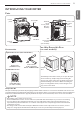
INTRODUCING YOUR DRYER 9 INTRODUCING YOUR DRYER ENGLISH Parts Control panel Reversible door Lint filter Leveling feet Terminal block access panel (Electric models) Power cord location (Gas models) Gas connection location (Gas models) Exhaust duct outlet Two-Way Reversible Door (on some models) Accessories Optional Accessories ( Not on all models ) Release Drying rack (3750EL0001C) Included Accessories Side vent kit (sold separately) Kit No.
INTRODUCING YOUR DRYER Control Panel Features Following are instructions for starting and using your new dryer. Please refer to specific sections of this manual for more detailed information. wWarning To reduce the risk of fire, electric shock, or injury to persons, read this entire manual, including the Important Safety Instructions, before operating this dryer. F B C A E A POWER ON/OFF BUTTON Press to turn the dryer ON. Press again to turn the dryer OFF.
INTRODUCING YOUR DRYER DisplayE 11 D G wWarning To reduce the risk of fire, electric shock, or injury to persons, read this entire manual, including the Important Safety Instructions, before operating this dryer. D C B A Estimated Time Remaining When the START/PAUSE button is pressed, the dryer will display the estimated (SENSOR DRY) or set time (TIME DRY) remaining, and begin tumbling.
INSTALLATION INSTRUCTIONS INSTALLATION INSTRUCTIONS Preview Installation Order Checking and choosing the proper location Leveling the dryer Venting the dryer 120V (Gas) Connecting gas dryers Connecting electric dryers Press and hold Installation test (Refer to page 34.
INSTALLATION INSTRUCTIONS 13 Installation Location Requirements ENGLISH wWarning Read all installation instructions completely before installing and operating your dryer! It is important that you review this entire manual before installing and using your dryer. Detailed instructions concerning electrical connections, gas connections, and exhaust requirements are provided on the following pages. •A location that allows for proper exhaust installation. A gas dryer must be exhausted to the outdoors.
INSTALLATION INSTRUCTIONS 1"* 30" 5"** (2,5 cm) (76,1 cm) (12,7 cm) Clearances (cont.) Recommended Installation Spacing For Cabinet Installation • F or cabinet installation with a door, minimum ventilation openings in the top of the cabinet are required. 7"* (17.8 cm) *Required spacing 7"* (17.8 cm) **For side or bottom venting, 2 inches (5.1 cm) spacing is allowed. 5"* 28 1"* (12.7 cm) (73.4 cm) (2.5 cm) 1" 27 " (2.54 cm) (68.6 cm) 1" (2.
INSTALLATION INSTRUCTIONS 15 Reversing the Door NOTE Service calls to reverse the door are not covered under the product warranty. • The door reversal process for the two-way door is more complex than for a conventional dryer door. Read through these instructions in their entirety before beginning the process, in order to gauge whether to have the procedure done by a professional installer or service person. • A support video is also provided at http://www. lg.
INSTALLATION INSTRUCTIONS 4. W ith the door on a protected surface, remove the 16 screws on each side of the door and lift off the inner door frame using a flat blade screwdriver. Remove the latch hook and blank and install them on the opposite side. 7. Reinstall the door. While supporting the door, install the four hinge screws removed in step 2.
INSTALLATION INSTRUCTIONS 3. R everse the components on the cabinet. latch mechanism Hinge Upper hinge e. Remove the three screws on the hinge at the bottom left. Remove the hinge and reinstall it on the right side. The top screw will occupy the hole where you removed the screw behind the hinge bracket in step d. Latch hole cover Hinge bracket a. U se a Phillips screwdriver to remove the two screws and the latch mechanism on the front panel of the cabinet. b.
INSTALLATION INSTRUCTIONS 5. S witch the door strike and the blank cover. Remove the two screws on the door cover that secure the door strike. Switch the door strike and the blank cover, installing them on the opposite sides from which they were removed. Short screws Blank cover Long screw Door strike Pull Raise Remove blank cover Gently pry out the hole plug on the side of the door cover and install it in the hole on the opposite side. Hole plug Set the door cover aside.
INSTALLATION INSTRUCTIONS 19 Top interlock buttons Inner lock rods Upper hinge assembly Upper hinge filter Upper hinge pivot Top lock rod Side lock rod Glass Side Interlock button Lower hinge filler Lower hinge assembly Lower hinge bracket Bumpers Interlock buttons Low hinge filler Side lock rod Top lock rod Inner lock rods Lower hinge bracket Hole plug Lower hinge assembly Upper hinge assembly Upper hinge pivot Upper hinge filler ENGLISH 6. R everse the components inside the door.
INSTALLATION INSTRUCTIONS 7. L ift out the gray interlock button in the side of the door. Make sure to remove the spring with the interlock button and to keep the two together. Set the interlock button aside. Do not confuse these with the interlock buttons from the top of the outer door. 10. Remove the upper hinge pivot. Once the top lock rod has been removed, the hinge pivot can easily be removed from the hinge assembly on the upper left and set aside. Upper hinge assembly Upper hinge pivot 8.
INSTALLATION INSTRUCTIONS c. F lip over the lower hinge bracket and release the tabs on the back locking the hinge filler to the hinge bracket. a. Insert the right end of the lock rod into the right hinge assembly. Make sure the rod is aligned with the guides in the door panel. Tab d. R otate the hinge 180 degrees and snap it back onto the front of the hinge bracket facing in the opposite direction. b.
INSTALLATION INSTRUCTIONS 15. R einstall the side interlock button. Reinstall the side interlock button removed in step 7. Center the spring in the compartment and insert the interlock button on top of it. 16. R einstall the door cover. Clean the glass on the door and door cover, if necessary. Make sure the three gray interlock buttons are properly installed and that the top and side lock rods are properly aligned where they meet.
INSTALLATION INSTRUCTIONS 23 Installing the Side Vent Kit • Use a heavy metal vent. • Do not use plastic or thin foil duct. • Clean old ducts before installing this dryer. • To reduce the risk of injury to persons, adhere to all industry recommended safety procedures including the use of long sleeved gloves and safety glasses. • F ailure to follow all of the safety warnings in this manual could result in property damage, injury to persons, or death. 3. P reassemble a 4 inches (10.
INSTALLATION INSTRUCTIONS Venting the Dryer wWarning To reduce the risk of fire, electric shock, or injury to persons when using this appliance, follow basic precautions, including the following: • Do not crush or collapse ductwork. Failure to follow these instructions can result in fire or death. • Do not allow ductwork to rest on or contact sharp objects. Failure to follow these instructions can result in fire or death.
INSTALLATION INSTRUCTIONS 25 Venting the Dryer (cont.) Wall Cap Type Number Of 90° Elbows Maximum Length Of 4-inch Diameter Rigid Metal Duct Recommended 0 65 ft. (19.8 m) 1 55 ft. (16.8 m) 2 47 ft. (14.3 m) 3 36 ft. (11.0 m) 4 28 ft. (8.5 m) 0 55 ft. (16.8 m) 1 47 ft. (14.3 m ) 2 41 ft. (12.5 m) 3 30 ft. (9.1 m) 4 22 ft. (6.7 m) 4" (10.2 cm) 4" (10.2 cm) Use only for short run installations 22/4" (6.35 cm) NOTE educt 6 ft. (1.8 m) for each additional elbow.
INSTALLATION INSTRUCTIONS Connecting Gas Dryers wWarning To reduce the risk of fire, electric shock, or injury to persons when using this appliance, follow basic precautions, including the following: •G as supply requirements: As shipped from the factory, this dryer is configured for use with natural gas. It can be converted for use with LP (Liquefied Propane) gas. Gas pressure must not exceed 13 inches of water column.
INSTALLATION INSTRUCTIONS 27 Connecting Gas Dryers (cont.) Connecting the gas supply To reduce the risk of fire, electric shock, or injury to persons when using this appliance, follow basic precautions, including the following: 1. M ake sure that the gas supply to the laundry room is turned OFF. Confirm that the type of gas available in your laundry room is appropriate for the dryer. The dryer is prepared for Natural Gas with a 3⁄₈ - inch NPT gas connection.
INSTALLATION INSTRUCTIONS Connecting Electric Dryers wWarning wWarning To help prevent fire, electric shock, serious injury, or death, the wiring and grounding must conform to the latest edition of the National Electrical Code, ANSI/NFPA 70 and all applicable local regulations. Please contact a qualified electrician to check your home’s wiring and fuses to ensure that your home has adequate electrical power to operate the dryer.
INSTALLATION INSTRUCTIONS 29 wWarning •C onnect the power cord to the terminal block. Connec teach power cord wire to the terminal block screw that has the same colored wire. For example, connect the black power cord wire to the terminal block screw with the black wire. Failure to follow these instructions may result in a short, overload, fire or death.
INSTALLATION INSTRUCTIONS Connecting Electric Dryers (cont.) USA only wWarning •C onnect the power cord to the terminal block. Connect each power cord wire to the terminal block screw that has the same colored wire. For example, connect the black power cord wire to the terminal block screw with the black wire. Failure to follow these instructions may result in a short, overload, fire or death.
INSTALLATION INSTRUCTIONS 31 wWarning •C onnect the power cord to the terminal block. Connect each power cord wire to the terminal block screw that has the same colored wire. For example, connect the black power cord wire to the terminal block screw with the black wire. Failure to follow these instructions may result in a short, overload, fire or death.
INSTALLATION INSTRUCTIONS Connecting Electric Dryers (cont.) USA only wWarning •C onnect the power cord to the terminal block. Connect each power cord wire to the terminal block screw that has the same colored wire. For example, connect the black power cord wire to the terminal block screw with the black wire. Failure to follow these instructions may result in a short, overload, fire or death.
INSTALLATION INSTRUCTIONS Any installation in a manufactured or mobile home must comply with the Manufactured Home Construction and Safety Standards Title 24 CFR, Part 3280 or Standard CAN/CSA Z240 MH and local codes and ordinances. If you are uncertain whether your proposed installation will comply with these standards, please contact a service and installation professional for assistance. •A gas dryer must be permanently attached to the floor.
INSTALLATION INSTRUCTIONS Installation Test (Duct check) Once you have completed the installation of the dryer, use this test to make sure the condition of the exhaust system is adequate for proper operation of the dryer. This test should be performed to alert you to any serious problems in the exhaust system of your home. F •Y our dryer features Flow Sense™, an innovative sensing system that automatically detects blockages and restrictions in dryer ductwork.
INSTALLATION INSTRUCTIONS 35 Installation Test (Duct check) (cont.) ENGLISH • Check the error code before you call for service Error Code tE1 or tE2 HS PS or PF or nP Possible Causes Solutions • Temperature sensor failure • T urn off the dryer and call for service. • Humidity sensor failure. • T urn off the dryer and call for service. • Electric dryer power cord is not connected correctly, or house power supply is incorrect.
C HOW TO USE How to use E Operating the Dryer G B D C Clean the Lint Filter 1 G 2 Lint Filter D If the lint filter has not already been cleaned, lift out the filter and remove the lint from the last load. This will help ensure the fastest and most efficient drying performance. Load the Dryer Load the dryer with the wet laundry from the washer. If the load is extra large, you may need to divide it into smaller loads for proper performance and fabric care.
HOW TO USE 37 Cycle Guide Cycle Fabric Type Do not use this ANTIBACTERIAL cycle with delicate fabrics. SENSOR DRY Dry Level Temperature Time in Min. Very Dry HEAVY DUTY Jeans, heavyweight Normal Dry items Adjustable PERM PRESS CASUAL Permanent press, synthetic items Normal Dry COTTON/ NORMAL Work clothes, corduroys, etc.
HOW TO USE Following are instructions for starting and using your new dryer. Please refer to specific sections of this manual for more detailed information. Sorting Load Check the Lint Filter Before Every Load Fabric care labels Most articles of clothing feature fabric care labels that include instructions for proper care. To clean, pull the lint filter straight up and roll any lint off the filter with your fingers. Do not rinse or wash the filter to remove lint.
HOW TO USE Using the LG EasyLoad™ Use the swing door when unloading, or when loading bulkier items, for easy access to the drum. To open the swing door, grasp the top of the door on the side opposite the hinge and pull. NOTE Make sure the hamper door release is completely closed before using the swing door. Hamper Door (on some models) Use the hamper door when loading.
HOW TO USE Cycle Settings And Options Sensor dry cycles have preset settings that are selected automatically. Manual dry cycles have default settings, but you may also customize the settings using the cycle setting buttons. Press the button for that option to view and select other settings. NOTE To protect your garments, not every dryness level, temperature, or option is available with every cycle. See the Cycle Guide for details. Dry Level Selects the level of dryness for the cycle.
HOW TO USE 41 Custom Program NOTE You may save only one custom program at a time. Pressing and holding the Custom Program button will overwrite any previously saved custom program. To recall a custom program: 1. Turn on the dryer. 2. Press the Custom Program button. 3. Press the Start/Pause button to start the cycle. ENGLISH If you have a special combination of settings that you use frequently, you can save these settings as a custom program.. * To save a custom program: 1.
MAINTENANCE MAINTENANCE Regular Cleaning Cleaning the lint filter wWarning Always clean the lint from the filter after every cycle. To reduce the risk of fire, electric shock, or injury to persons when using this appliance, follow basic precautions, including the following: •U nplug the dryer before cleaning to avoid the risk of electric shock. Failure to follow this warning can cause serious injury, fire, electrical shock, or death.
TROUBLESHOOTING 43 Before Calling For Service Your dryer is equipped with an automatic error-monitoring system to detect and diagnose problems at an early stage. If your dryer does not function properly or does not function at all, check the following before you call for service. Problem Possible Causes Solutions Dryer will not turn on •P ower cord is not properly plugged in. •H ouse fuse is blown, circuit breaker has tripped, or power outage has occurred.
TROUBLESHOOTING Before Calling For Service (cont.) Problem Possible Causes Solutions Drying time is not consistent • Heat settings, load size, or dampness of clothing is not consistent. • The drying time for a load will vary depending on the heat setting, the type of heat used (electric, natural gas, or LP gas), the size of the load, the type of fabrics, the wetness of the clothes, and the condition of the exhaust ducts and lint filter.
SPECIFICATIONS 45 SPECIFICATIONS DLE4970WE Description Dryer DLG4971WE Electrical requirements Please refer to the rating label regarding detailed information. Gas requirements NG: 4-10.5 inches WC LP: 8–13 inches WC Dimensions 27” (W) X 28 15/16” (D) X 45 7/16” (H), 50 1/4” (D with door open) 68.6 cm (W) X 73.4 cm (D) X 115.3 cm (H), 127.5 cm (D with door open) Net weight Electric : 122.4 lb (55.5 kg) Gas : 125.7 lb (57 kg) Drying capacity - Normal cycle IEC 7.3 cu.ft. (22.5 lb/10.
USING SMART DIAGNOSIS™ USING Smart DiagnosisTM Should you experience any problems with your dryer, it has the capability of transmitting data to your Smart Phone using the LG Smart Laundry Application or via your telephone to the LG call center. Smart Diagnosis™ cannot be activated unless your dryer is turned on by pressing the Power button. If your dryer is unable to turn on, then troubleshooting must be done without using Smart Diagnosis™.
WARRANTY 47 Should your LG Dryer (“Product”) fail due to a defect in materials or workmanship under normal home use, during the warranty period set forth below, LG will at its option repair or replace the product. This limited warranty is valid only to the original retail purchaser of the product and applies only when purchased and used within the United States including U.S. Territories. Proof of original retail purchase is required to obtain warranty service under this limited warranty.
•• Costs associated with removal of your Product from your home for repairs. •• The removal and reinstallation of the Product if it is installed in an inaccessible location or is not installed in accordance with published installation instructions, including LG’s owner’s and installation manuals. •• Damage resulting from misuse, abuse, improper installation, repair, or maintenance. Improper repair includes use of parts not approved or specified by LG. Filter is clogged.
esPaÑol ManUal de propieTario secadora lea este manual de usuario detenidamente antes de la utilizacion y guardelo a mano para futuras consultas. dle4970*e dlg4971*e www.lg.
2 Tabla de contenidos Tabla de contenidos 3 INSTRUCCIONES IMPORTANTES DE SEGURIDAD 3 Qué hacer si huele gas 4 Precauciones básicas de seguridad 4 Ley ejecutiva para la seguridad del agua potable y los tóxicos de California (California Safe Drinking Water and Toxic Enforcement Act) 5 Instrucciones de conexión a tierra 5 Instrucciones importantes para la instalación 7 Instrucciones importantes para conectar la electricidad 36 CÓMO USAR 36 Funcionamiento de la secadora 37 Guía de ciclos 38 Clasifica
INSTRUCCIONES IMPORTANTES DE SEGURIDAD 3 INSTRUCCIONES IMPORTANTES DE SEGURIDAD LEA TODAS LA INSTRUCCIONES ANTES DE USAR wadvertencia Su Seguridad y la de los demás son de suma importancia. E n este manual y en su electrodoméstico figuran muchos mensajes importantes de seguridad. Lea y cumpla siempre con todos los mensajes de seguridad. Éste es el símbolo de alerta de seguridad. El mismo alerta sobre potenciales riesgos de muerte o heridas tanto para usted como para otras personas.
4 INSTRUCCIONES IMPORTANTES DE SEGURIDAD INSTRUCCIONES IMPORTANTES DE SEGURIDAD LEA TODAS LA INSTRUCCIONES ANTES DE USAR wadvertencia Por su seguridad, debe seguir la información indicada en este manual para minimizar el riesgo de incendio o explosión, descarga eléctrica, o para prevenir daños a la propiedad, lesiones personales o muerte.
INSTRUCCIONES IMPORTANTES DE SEGURIDAD 5 INSTRUCCIONES IMPORTANTES DE SEGURIDAD LEA TODAS LA INSTRUCCIONES ANTES DE USAR wadvertencia INSTRUCCIONES DE CONEXIÓN A TIERRA Este electrodoméstico deberá estar conectado a tierra. En caso de avería o mal funcionamiento, la conexión a tierra reducirá el riesgo de descargas eléctricas al brindar un camino con una resistencia menor para la corriente eléctrica.
6 INSTRUCCIONES IMPORTANTES DE SEGURIDAD INSTRUCCIONES IMPORTANTES DE SEGURIDAD LEA TODAS LA INSTRUCCIONES ANTES DE USAR wadvertencia Por su seguridad, debe seguir la información indicada en este manual para minimizar el riesgo de incendio o explosión, descarga eléctrica, o para prevenir daños a la propiedad, lesiones personales o muerte.
INSTRUCCIONES IMPORTANTES DE SEGURIDAD 7 INSTRUCCIONES IMPORTANTES DE SEGURIDAD LEA TODAS LA INSTRUCCIONES ANTES DE USAR wadvertencia Instrucciones importantes para conectar la electricidad wadvertencia Para reducir el riesgo de incendio, descargas eléctricas o heridas al usar su electrodoméstico, siga las precauciones básicas, incluyendo lo siguiente: • Bajo ninguna circunstancia, corte o quite la tercera pata (puesta a tierra) del cable eléctrico.
CARACTERÍSTICAS DEL PRODUCTO CARACTERÍSTICAS DEL PRODUCTO PANEL DE CONTROL FÁCIL PARA USAR Una amplia selección de funciones sencillas de usar para facilitar la operación de la secadora. Puerta reversible de doble sentido para un fácil acceso La función LG EasyLoad™ le permite abrir la puerta desde la parte superior, por lo que podrá cargar la secadora de forma sencilla sin que se le caigan las prendas al suelo.
la introducción de la secadora 9 la introducción de la secadora Partes Puerta reversible Filtro de pelusa Patas niveladoras Panel de acceso del bloque terminal (Modelos eléctricos) Ubicación de la toma de gas (Modelos a gas) Ubicación del cable eléctrico (Modelos a gas) Salida del conducto de escape Puerta reversible de doble sentido (en algunos modelos) Accesorios Accesorios opcionales Apertura Secado en parrilla (3750EL0001C) Kit de ventilación lateral (se vende por separado) N.
10 la introducción de la secadora Características del panel de control A continuación encontrará instrucciones para comenzar a usar su secadora nueva. Para más información por favor consulte las secciones específicas de este manual. wadvertencia Para reducir el riesgo de incendios, descargas eléctricas o heridas, lea este manual en su totalidad, incluyendo las Instrucciones Importantes de Seguridad, antes de operar la secadora.
la introducción de la secadora E Pantalla 11 D G La pantalla muestra los ajustes, el tiempo restante estimado, las opciones y los mensajes de estado correspondientes a su secadora. Cuando se gira el secador, la luz en la exhibición iluminará. wadvertencia D C B A Tiempo restanterestante estimado (ESTIMATED TIME REMAINING) Cuando se presiona el boton INICIO/PAUSA (START/ PAUSE), la pantalla indicara el tiempo restante estimado para el ciclo de secado seleccionado.
12 INSTRUCCIONES PARA LA INSTALACIÓN INSTRUCCIONES PARA LA INSTALACIÓN Vista previa del orden de instalación Comprobación y elección de la ubicación adecuada Nivelación de la secadora ventilación de la secadora 120V (Gas) Conexión de secadoras a gas Cómo conectar las secadoras eléctricas Pulse y mantenga Test de Instalación (consulte la página 34) Prueba de funcionamiento 240V (Eléctricos) Conexión del enchufe y la toma de tierra
INSTRUCCIONES PARA LA INSTALACIÓN 13 Requisitos del lugar de instalación wadvertencia • Un lugar que permita la instalación correcta del sistema de escape. El secador de gas debe tener una salida de escape hacia el exterior. Consulte Requisitos de ventilación. • La salida eléctrica de toma a tierra debe estar a 61 cm (2 pies) de ambos lados de la secadora.Consulte Requisitos eléctricos. • El suelo debe ser firme para soportar el peso total de la secadora, siendo éste de 90,7 kg (200 lbs).
) * 5 cm) (99,1 cm) 14 INSTRUCCIONES PARA LA INSTALACIÓN 1"* 30" 5"** (2,5 cm) (76,1 cm) (12,7 cm) 1"* (2,5 cm) 24 in.2* (155 cm2) 3"* (7,6 cm) 5"** 30" (76,1 cm) (12,7 cm) 1" (2,5 cm) 27" (68,6 cm) 1" (2,5 cm) 1" (2,5 cm) Espacios de instalación (cont.) Separación recomendada para la instalación en un habitáculo cerrado •A l realizar la instalación en un habitáculo cerrado debe haber salidas de ventilación mínimas en la parte superior e inferior del lugar.
INSTRUCCIONES PARA LA INSTALACIÓN 15 Inversión de la puerta Antes de comenzar NOTA 1. Abra la puerta de costado de manera de poder acceder a los tornillos de las bisagras. 2. Extraiga los cuatro tornillos de las bisagras Mientras sostiene a la puerta, extraiga los cuatro tornillos de las bisagras, dos de cada bisagra. Aparte la puerta: colóquela de cara al suelo sobre una superficie protegida para evitar que se dañe la puerta o la superficie de trabajo.
16 INSTRUCCIONES PARA LA INSTALACIÓN 4. C on la puerta colocada sobre una superficie protegida, retire los 16 tornillos de cada lado de la puerta y retire el panel interior de la puerta con un destornillador de punta plana. Retire el enganche y la pieza, y llévelas al lado opuesto. 7. Reinstale la puerta. Mientras sujeta la puerta, instálela con los cuatro tornillos de bisagra retirados en el paso 2.
INSTRUCCIONES PARA LA INSTALACIÓN 3. I nvierta los componentes del gabinete. Cubierta de la bisagra Bisagra e. Extraiga los tres tornillos de la bisagra inferior izquierda. Extraiga la bisagra y vuelva a instalarla en el lado derecho. El tornillo superior ocupará el agujero de donde extrajo el tornillo detrás del soporte de la bisagra en el paso d. Cubierta del agujero del pestillo Soporte de la bisagra a.
18 INSTRUCCIONES PARA LA INSTALACIÓN 5. I ntercambie la cerradura de la puerta y la cubierta ciega. Extraiga los dos tornillos de la cubierta de la puerta que sujetan la cerradura de la puerta. Intercambie la cerradura de la puerta y la cubierta ciega e instálelas en el lado opuesto del lado de donde las extrajo.
INSTRUCCIONES PARA LA INSTALACIÓN 19 6. I nvierta los componentes de la parte interior de la puerta. Ahora retirará e invertirá varios componentes de la parte interior de la puerta. Aquí abajo encontrará un diagrama detallado con la identificación de la estructura interna y las partes de la puerta. (El diagrama muestra la “vista anterior” de la puerta, con la distribución predeterminada para una apertura con la bisagra del lado derecho.
20 INSTRUCCIONES PARA LA INSTALACIÓN 7. R etire el botón de bloqueo de color gris del costado de la puerta. Asegúrese de extraer el resorte con el botón de bloqueo y de conservar las dos piezas juntas. Aparte el botón de bloqueo. No lo mezcle con los botones de bloqueo de la parte superior de la puerta exterior. 10. Extraiga el pivote de la bisagra superior.
INSTRUCCIONES PARA LA INSTALACIÓN 12. Vuelva a instalar la barra de bloqueo superior. Gire la barra de bloqueo superior (extraída en el paso 10) 180 grados en la posición contraria a su posición original y vuelva a instalarla. El resorte ahora debe encontrarse hacia la derecha del centro, con el resorte del costado de la barra orientado hacia la parte superior de la puerta. 21 c.
22 INSTRUCCIONES PARA LA INSTALACIÓN 15. Vuelva a instalar el botón de bloqueo lateral. Vuelva a instalar el botón de bloqueo lateral extraído en el paso 7. Coloque el resorte en el centro del compartimiento e inserte el botón de bloqueo arriba del resorte. 16. Vuelva a instalar la cubierta de la puerta. Limpie el cristal de la puerta y de la cubierta de la cubierta si fuera necesario.
INSTRUCCIONES PARA LA INSTALACIÓN 23 Instalacion del kit de ventilacion lateral wadvertencia • Utilice material para ventilación de metal pesado. • No utilice conductos de plástico o aluminio delgado. • Para reducir el riesgo de lesiones personales, cumpla con todos los procedimientos de seguridad recomendados por la industria, incluyendo el uso de use guantes con mangas largas y gafas de seguridad.
24 INSTRUCCIONES PARA LA INSTALACIÓN Cónexión del conducto de ventilación de la secadora wadvertencia Para reducir el riesgo de incendio, descargas eléctricas o heridas al usar su electrodoméstico, siga las precauciones básicas, incluyendo lo siguiente: • No aplaste ni doble el sistema de conducto. Si no se siguen estas instrucciones se podrá producir incendio o muerte. • No permita que el sistema de conducto se asiente sobre objetos puntiagudos ni entre en contacto con los mismos.
INSTRUCCIONES PARA LA INSTALACIÓN 25 Conexión del conducto de ventilación de la secadora (cont.) Sistema de conducto Recomendado 4" (10.2 cm) 4" (10.2 cm) Solamente para el uso en los instalaciones de conducto cortos 22/4" (6.35 cm) Número De Long . Máx. De Conduc Codos To Metálico Fle Xible De 90° De Diám.
26 INSTRUCCIONES PARA LA INSTALACIÓN Conexión de secadoras a gas wadvertencia Para reducir el riesgo de incendio, descargas eléctricas o heridas al usar su electrodoméstico, siga las precauciones básicas, incluyendo lo siguiente: • Requisitos de suministro de gas: Como enviado de fábrica, si configura la secadora para uso con gas natural. Puede convertirse para usar con gas LP (propano líquido). La presión de gas no debe sobrepasar la columna de agua de 13 pulgadas.
INSTRUCCIONES PARA LA INSTALACIÓN 27 Connecting gas dryers (cont.) Conexión del suministro de gas Para reducir el riesgo de incendio, descargas eléctricas o heridas al usar su electrodoméstico, siga las precauciones básicas, incluyendo lo siguiente: 1. A segúrese de que el suministro de gas al cuarto de lavado se encuentre APAGADO.Confirme que el tipo de gas disponible en su cuarto de lavado sea el adecuado para la secadora. La secadora está lista para la conexión de gas natural de 3⁄₈ pulgadas NPT.
28 INSTRUCCIONES PARA LA INSTALACIÓN Cómo conectar las secadoras eléctricas wadvertencia wadvertencia Para ayudar a evitar incendios, descargas eléctricas, heridas graves o muerte, el cableado e instalación a tierra deben cumplir con la última edición del Código Eléctrico Nacional, ANSI/NFPA 70 y todas las regulaciones locales aplicables.
INSTRUCCIONES PARA LA INSTALACIÓN 29 Cómo conectar las secadoras eléctricas (cont.) SÓLO EE.UU. wadvertencia •C ontacto por conductor neutro está prohibido para: (1) nuevas instalaciones de circuito derivado, (2) las casas móviles, (3) vehículos recreacionales, y (4) áreas donde los códigos prohíben una conexión a tierra por el conductor neutro.
30 INSTRUCCIONES PARA LA INSTALACIÓN Cómo conectar las secadoras eléctricas (cont.) SÓLO EE.UU. wadvertencia • Conecte el cable de alimentación a la caja de terminales. Conecte cada uno de los conductores del cable de alimentación al tornillo de la caja de terminales que tenga el conductor del mismo color. Por ejemplo, conecte el conductor negro del cable de alimentación al tornillo de la caja de terminales que tiene el conductor negro.
INSTRUCCIONES PARA LA INSTALACIÓN 31 Cómo conectar las secadoras eléctricas (cont.) SÓLO EE.UU. wadvertencia • Contacto por conductor neutro está prohibido para: (1) nuevas instalaciones de circuito derivado, (2) las casas móviles, (3) vehículos recreacionales, y (4) áreas donde los códigos prohíben una conexión a tierra por el conductor neutro.
32 INSTRUCCIONES PARA LA INSTALACIÓN Cómo conectar las secadoras eléctricas (cont.) SÓLO EE.UU. wadvertencia • Conecte el cable de alimentación a la caja de terminales. Conecte cada uno de los conductores del cable de alimentación al tornillo de la caja de terminales que tenga el conductor del mismo color. Por ejemplo, conecte el conductor negro del cable de alimentación al tornillo de la caja de terminales que tiene el conductor negro.
INSTRUCCIONES PARA LA INSTALACIÓN Requisitos especiales para viviendas móviles o prefabricadas •U na secadora de gas debería fijarse permanentemente sobre el piso. • L a conexión eléctrica de una secadora eléctrica debe ser una conexión de 4 hilos. Se provee información más detallada pertinente a la conexión eléctrica en la sección Cómo conectar las secadoras eléctricas. •P ara reducir el riesgo de combustión e incendio, se debe ventilar la secadora hacia el exterior.
F 34 INSTRUCCIONES PARA LA INSTALACIÓN Test de Instalación (conducto de comprobar) Una vez haya instalado la secadora, haga este test para asegurarse de que las condiciones del sistema de evacuación son las adecuadas para el funcionamiento correcto de la secadora. Este test tiene como objetivo mostrarle si existe algún problema importante en el sistema de evacuación de su vivienda.
INSTRUCCIONES PARA LA INSTALACIÓN 35 Test de Instalación (conducto de comprobar) (cont.) •C ompruebe el código de error antes de llamar al servicio técnico Código de error HS PS o PF o nP Soluciones •A pague la secadora y llame al servicio técnico. • Fallo del sensor de humedad. •A pague la secadora y llame al servicio técnico. • El cable de alimentación no está conectado correctamente o el suministro eléctrico de la vivienda es incorrecto.
36 C CÓMO USAR CÓMO USAR E G Funcionamiento de la secadora B LimpiarCEl Filtro De Pelusas 1 Filtro de pelusa 2 D G D Si aún no ha limpiado el filtro de pelusas, extráigalo y elimine las pelusas procedentes de la última carga. Esto le ayudará a asegurar un funcionamiento más rápido y eficiente de secado. Cargar La Secadora Cargue en la secadora la carga húmeda procedente de la lavadora.
CÓMO USAR 37 Guía de ciclos Type secado manual Fabric Type Dry Level ANTIBACTERIAL No utilizar este ciclo con prendas delicadas. SECADO INTENSO Vaqueros, prendas pesadas. Normal seco PLANCHADO PERM., INFORMAL Prendas sintéticas, planchado permanente. Normal seco ALGODÓN/ NORMAL Ropa de trabajo, pana, etc. Normal seco DELICADO Lencería, sábanas, blusas Normal seco POCA CARGA Sólo prendas Normal seco normales y de algodón/tipo toallas (máx. aprox.
38 CÓMO USAR A continuación encontrará instrucciones para comenzar a usar su secadora nueva. Para más información por favor consulte las secciones específicas de este manual. Clasificación de cargas Revise el filtro de pelusa antes de cada uso Etiquetas de mantenimiento de las telas La mayoría de las prendas de vestir tienen etiquetas de mantenimiento de las telas para lograr un mantenimiento adecuado.
CÓMO USAR Uso de la función LG EasyLoad™ Puerta abatible Utilice la puerta abatible para cargar o descargar prendas más voluminosas y así para tener un fácil acceso al tambor. NOTA Asegúrese de que el dispositivo de abertura de la puerta de apertura superior esté completamente cerrado antes de usar la puerta abatible.
40 CÓMO USAR Botones de ajuste de ciclos Los ciclos de secado con sensor (sensor dry) tienen ajustes preprogramados que se seleccionan automaticamente. Los ciclos de csecado manual (manual dry) tienen ajustes predeterminados, pero pueden Personalizarse usando los botones de ajustes de ciclos. Apriete el botón de esa opción para ver y seleccionar otros ajustes. NOTA Para proteger las prendas, no todos los niveles de secado, temperatura u opción están disponibles en todos los ciclos.
CÓMO USAR 41 Programa personalizado NOTA Puede guardar solo un programa personalizado a la vez. Al apretar y mantener apretado el botón Programa Personalizado (Custom Program), reemplazará cualquier programa personalizado que haya guardado anteriormente. Para recuperar un programa personalizado: 1. Encienda la secadora. 2. Apriete el botón Programa Personalizado (Custom Program). 3. Apriete el boton Inicio/Pausa (Start/Pause) para iniciar el ciclo.
42 MANTENIMIENTO MAINTENANCE Limpieza regular Limpieza del filtro de pelusa Limpie siempre las pelusas del filtro tras cada ciclo. wadvertencia Para reducir el riesgo de incendio, descargas eléctricas o heridas al usar su electrodoméstico, siga las precauciones básicas, incluyendo lo siguiente: • Desenchufe la secadora antes de limpiar la misma para evitar el riesgo de descargas eléctricas. Si no se cumple con esta advertencia se podrán producir heridas graves, incendios, descargas eléctricas o muerte.
RESOLUCIÓN DE PROBLEMAS 43 resoluciÓn de problemas Antes de llamar a mantenimiento Su secadora está equipada con un sistema de monitoreo de errores automático para la detección y el diagnóstico de problemas en una etapa temprana. Si su secadora no funciona adecuadamente o no funciona en lo absoluto, revise lo siguiente antes de llamar a mantenimiento. Causas posibles Soluciones • El cable eléctrico no está enchufado adecuadamente.
44 RESOLUCIÓN DE PROBLEMAS Antes de llamar a mantenimiento (cont.) Problem Possible Causes Solutions Las prendas tardan demasiado tiempo en secarse • La carga no está correctamente clasificada. • Separe los artículos pesados de los livianos. Los artículos más grandes y pesados requieren de mayor tiempo de secado. • Carga grande de telas pesadas. • Las telas pesadas requieren de mayor tiempo de secado ya que tienden a retener mayor humedad.
ESPECIFICACIONES 45 ESPECIFICACIONES DLE4970WE Descripción Secadora DLG4971WE Requisitos eléctricos Consulte la placa de clasificación para información en detalles. Requisitos de gas NG: 4 a 10.
46 Utilización del SMART DIAGNOSIS™ Utilización del Smart Diagnosis™ Si tuviera algún problema con su secadora, la misma posee la capacidad de transmitir datos a un teléfono inteligente utilizando la aplicación Smart Laundry de LG o mediante el teléfono al Centro de atención telefónica de LG. Smart Diagnosis™ no puede ser activado a menos que su secadora esté encendida pulsando el botón de Alimentación(Power).
GARANTÍA 47 GARANTÍA (EE. UU.) Período de garantía Alcance de la garantía Un (1) año a partir de la fecha de compra minorista original Piezas y mano de obra Diez (10) años a partir de la fecha de compra minorista original Tambor de la secadora CÓMO SE MANEJA EL SERVICIO TÉCNICO LG suministrará las piezas y la mano de obra para reparar o reemplazar las piezas defectuosas. Solo las piezas.
48 •• Reparaciones cuando el producto se use de otra forma que no sea uso doméstico usual y normal (p. ej., uso comercial, en oficinas e instalaciones recreativas) o contraria a las instrucciones esbozadas en el manual del propietario del producto. •• Costos asociados con el retiro del producto de su casa para realizar reparaciones.
49 ESPAÑOL
50
51 ESPAÑOL
LG Customer Information Center 1-800-243-0000 USA 1-888-542-2623 CANADA Register your product Online! www.lg.