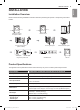
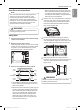
INSTALLATION ENGLISH INSTALLATION 9 Installation Overview Please read the following installation instructions first after purchasing this product or transporting it to another location.
10 INSTALLATION Installation Location Requirements Warning Read all installation instructions completely before installing and operating your dryer! It is important that you review this entire manual before installing and using your dryer. Detailed instructions concerning electrical connections, gas connections, and exhaust requirements are provided on the following pages. The installation requires: •• A location that allows for proper exhaust installation. A gas dryer must be exhausted to the outdoors.
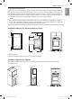
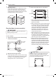
INSTALLATION 11 Closets with doors must have both an upper and lower vent to prevent heat and moisture buildup in the closet. One upper vent opening with a minimum opening of 48 sq. in. (310 cm2) must be installed no lower than 6 feet above the floor. One lower vent opening with a minimum opening of 24 sq. in. (155 cm2) must be installed no more than one foot above the floor. Install vent grills in the door or cut down the door at the top and bottom to form openings.
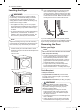
12 INSTALLATION Leveling the Dryer 2 Warning To reduce the risk of injury to persons, adhere to all industry recommended safety procedures including the use of long-sleeved gloves and safety glasses. Failure to follow this warning may result in serious injury or death. Use an adjustable wrench to turn the leveling feet. Unscrew the legs to raise the dryer or screw in the legs to lower it. Raise or lower with the leveling feet until the dryer is level from side to side and front to back.
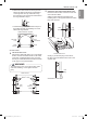
INSTALLATION 13 c. Remove the hinge cover by gently prying it up with a flat blade screwdriver, being careful not to scratch the paint. Rotate the hinge cover 180 degrees and install it on the opposite side, where the hinge was attached. NOTE The instructions here are for changing the door swing from a right to a left side hinge. If the door has been reversed, and it is necessary to change it back, use care when following these instructions.
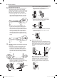
14 INSTALLATION 7 Reinstall the door. While supporting the door, install the four hinge screws removed in step 2. Test the swing of the door to make sure the hinges and latch are properly aligned and that the door opens, closes and latches properly in both directions. 3 Reverse the components on the cabinet. Hinge cover Upper hinge latch mechanism Latch hole cover Hinge Hinge bracket a. Use a Phillips screwdriver to remove the two screws and the latch mechanism on the front panel of the cabinet.
INSTALLATION 15 5 Switch the door strike and the blank cover. Remove the two screws on the door cover that secure the door strike. Switch the door strike and the blank cover, installing them on the opposite sides from which they were removed. f. Install the hinge bracket removed in step d on the bottom left side, first installing one screw behind the hinge bracket. Short screws ENGLISH e. Remove the three screws on the hinge at the bottom left. Remove the hinge and reinstall it on the right side.
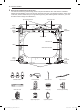
16 INSTALLATION 6 Reverse the components inside the door. You will now be removing and reversing various components inside the door. See below for a detailed diagram and identification of the inner structure and parts of the door. (The diagram shows the “before view” of the door, with the default set-up for a right side hinge swing. After following these instructions, your door should be a mirror image of the illustration.
INSTALLATION 17 Lift out the gray interlock button in the side of the door. Make sure to remove the spring with the interlock button and to keep the two together. Set the interlock button aside. Do not confuse these with the interlock buttons from the top of the outer door. 10 Remove the upper hinge pivot. Once the top lock rod has been removed, the hinge pivot can easily be removed from the hinge assembly on the upper left and set aside.
18 INSTALLATION 12 c. Flip over the lower hinge bracket and release the tabs on the back locking the hinge filler to the hinge bracket. Reinstall the top lock rod. Rotate the top lock rod (removed in step 10) 180 degrees end for end from its original position and reinstall it. The spring should now be to the right of center, with the spring on the side of the rod facing the top of the door. a. Insert the right end of the lock rod into the right hinge assembly.
INSTALLATION 19 Reinstall the side interlock button. Reinstall the side interlock button removed in step 7. Center the spring in the compartment and insert the interlock button on top of it. 16 Reinstall the door cover. Clean the glass on the door and door cover, if necessary. Make sure the three gray interlock buttons are properly installed and that the top and side lock rods are properly aligned where they meet.
20 INSTALLATION Installing the Side Vent Kit 3 Warning •• Use a heavy metal vent. •• Do not use plastic or thin foil ducts. •• Clean old ducts before installing this dryer. •• To reduce the risk of injury to persons, adhere to all industry recommended safety procedures including the use of long-sleeved gloves and safety glasses. •• Failure to follow all of the safety warnings in this manual could result in property damage, injury to persons, or death. Preassemble a 4-inch (10.
INSTALLATION 21 Warning To reduce the risk of fire or explosion, electric shock, property damage, injury to persons or death when using this appliance, follow basic safety precautions, including the following: •• Do not crush or collapse ductwork. Failure to follow these instructions may result in fire or death. •• Do not allow ductwork to rest on or contact sharp objects. Failure to follow these instructions may result in fire or death.
22 INSTALLATION Routing And Connecting Ductwork NOTE Follow the guidelines below to maximize drying performance and reduce lint buildup and condensation in the ductwork. Ductwork and fittings are NOT included and must be purchased separately. •• Use 4-inch (10.2 cm) diameter rigid, semi-rigid or flexible metal ductwork. •• The exhaust duct run should be as short as possible. •• Use as few elbow joints as possible. •• The male end of each section of exhaust duct must point away from the dryer.
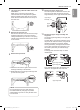
INSTALLATION 23 d. Connect the long dryer hose to one side of the Y-connector and connect the washer hose to the other side. The dryer must be connected to the cold water tap using a new water supply hose. Do not use old hoses. NOTE •• Water supply pressure must be between 20 and 120 psi (138—827 kPa) . •• Do not strip or cross-thread when connecting the inlet hose to the valve. •• If the water supply pressure is more than 800 kPa, a pressure-reducing valve should be installed.
24 INSTALLATION Connecting Gas Dryers Warning To reduce the risk of fire or explosion, electric shock, property damage, injury to persons, or death when using this appliance, follow basic safety precautions. Gas Supply Requirements •• As shipped from the factory, this dryer is configured for use with natural gas (NG). It can be converted for use with propane (LP) gas. Gas pressure must not exceed 8-inch (20.3 cm) water column for NG, or 13-inch (33 cm) water column for LP.
INSTALLATION 25 •• Installation and service must be performed by a qualified installer, service agency, or the gas supplier. Failure to do so may result in fire, explosion, or death. •• Use only a new stainless steel flexible connector and a new AGA-certified connector. Failure to do so may result in fire, explosion, or death. •• A gas shutoff valve must be installed within 6 ft. (1.8 m) of the dryer. Failure to do so may result in fire, explosion, or death.
26 INSTALLATION Connecting Electric Dryers Electrical Requirements for Electric Models Only Warning To help prevent fire, electric shock, serious injury, or death, the wiring and grounding must conform to the latest edition of the National Electrical Code, ANSI/NFPA 70 and all applicable local regulations. Please contact a qualified electrician to check your home’s wiring and fuses to ensure that your home has adequate electrical power to operate the dryer.
INSTALLATION 27 Connect the power cord to the terminal block. Each colored wire should be connected to the same color screw. Wire color indicated on manual is connected to the same color screw in the block. Failure to follow these instructions may result in a short or overload. Grounding through the neutral conductor is prohibited for: (1) new branch-circuit installations, (2) mobile homes, (3) recreational vehicles, and (4) areas where local codes prohibit grounding through the neutral conductor.
28 INSTALLATION Four-Wire Direct Wire •• A 4-wire connection is required for all mobile and manufactured home installations, as well as all new construction after January 1, 1996. •• A UL-listed strain relief is required. •• Use UL-listed 4-wire #10 AWG-minimum copper conductor cable. Allow at least 5 ft. (1.5 m) of wire to allow for removal and reinstallation of the dryer. 1 Remove 5-inch (12.7 cm) of the outer covering from the wire. Remove 5-inch (12.7 cm) of insulation from the ground wire.
INSTALLATION 29 8 Reinstall the terminal block access cover. Neutral Hot (Black) (White) •• A 3-wire connection is NOT permitted on new construction after January 1, 1996. Hot (Red) Ground Screw •• A UL-listed strain relief is required. •• Use a 30-amp, 240-volt, 3-wire, UL-listed power cord with #10 AWG-minimum copper conductor and closed loop or forked terminals with upturned ends. 1 Remove the terminal block access cover on the upper back of the dryer.
30 INSTALLATION Three-Wire Direct Wire 9 Reinstall the terminal block access cover. Hot (Black) •• A 3-wire connection is NOT permitted on new construction after January 1, 1996. •• A UL-listed strain relief is required. •• Use UL-listed 3-wire, #10 AWG-minimum copper conductor cable. Allow at least 5 ft. (1.5 m) length to allow for removal and installation of dryer. 1 Remove 3½-inch (8.9 cm) of the outer covering from the wire. Strip 1 inch (2.5 cm) insulation from each wire.
INSTALLATION 31 4 Once you have completed the installation of the dryer, use this test to make sure the condition of the exhaust system is adequate for proper operation of the dryer. This test should be performed to alert you to any serious problems in the exhaust system of your home. •• Your dryer features Flow Sense™, an innovative sensing system that automatically detects blockages and restrictions in dryer ductwork.
32 INSTALLATION •• Check the duct condition If the Flow SenseTM LED is turned on, check the exhaust system for restrictions and damage. Repair or replace the exhaust system as needed. Restricted or Blocked Airflow Avoid long runs or runs with multiple elbows or bends. NOTE When the dryer is first installed, this test should be performed to alert you to any existing problems with the exhaust duct in your home.