Website: http://us.lge.com Website: http://ca.lge.com Installation Manual Manual de instalación Manuel d'Installation 30” Electric Built-In Single and Double Wall Oven Horno eléctrico de pared empotrado simple y doble de 30” Four Mural Électrique Encastrable de 30po - Simple ou Double LWS3081ST LWD3081ST Please read these instructions thoroughly before installing and operating the oven. Tenga a bien leer estas instrucciones por completo antes de instalar y operar el horno.
Part 1 SAFETY 1 BEFORE YOU BEGIN Remove all tape and packing materials before using the oven. Dispose all plastic bags after unpacking the oven. Never allow children to play with packing materials. IMPORTANT SAFETY INSTRUCTIONS Read and follow all instructions before using your oven to prevent the risk of fire, electric shock, injury to person, or damage when using the oven. This guide does not cover all possible conditions that may occur.
Part 1 SAFETY IMPORTANT NOTE This installation must be completed by a qualified installer or technician. • Please read the entire Installation Instructions prior to installation. • Remove all packing materials from the oven compartments before connecting the electrical supply to the oven. • Installer: please retain these instructions for local inspector’s reference, then leave them with the consumer.
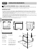
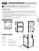
Part 2 INSTALLATION REQUIREMENTS 1 INSTALLATION DRAWINGS (FOR 30” SINGLE BUILT- IN OVEN) The first step of your installation should be to measure your current cutout dimensions and compare them to the cutout dimensions shown below. You may find little or no cabinet work will be necessary. IMPORTANT NOTE Product dimensions 27 3/8” (69.5 cm) Español English • The cabinet base platform must be able to support 190lbs (86Kg).
Part 2 INSTALLATION REQUIREMENTS 2 INSTALLATION DRAWINGS (FOR 30” DOUBLE BUILT- IN OVEN) The first step of your installation should be to measure your current cutout dimensions and compare them to the cutout dimensions shown below. You may find little or no cabinet work will be necessary. IMPORTANT NOTE • The cabinet base platform must be able to support 325lbs (147Kg).
Part 2 INSTALLATION REQUIREMENTS 3 INSTALLATION DRAWINGS (FOR 30” SINGLE BUILT- IN OVEN UNDERCOUNTER) The first step of your installation should be to measure your current cutout dimensions and compare them to the cutout dimensions shown below. You may find little or no cabinet work will be necessary. IMPORTANT NOTE English • The cabinet base platform must be able to support 190lbs (86Kg).
Part 2 INSTALLATION REQUIREMENTS 4 PREPARATION FOR MOVING THE OVEN The second step of your installation should be to remove any packing material from the oven before you install the oven. 1. Remove all tape from around the oven. 2. Open the oven door and remove packaging materials and oven racks inside the oven. 3. Door removal is not a requirement for installation of the oven, but is an added convenience. To remove the door, follow the steps below. Step. 1 Step. 3 Fully open the door. Slot Step.
Part 3 ELECTRICAL CONNECTIONS 1 ELECTRICAL CONNECTION REQUIREMENTS The third step of your installation should be to follow electrical connection requirements below. Dedicated circuit protection must be prepared as recommended in electrical connection requirements and the oven should be grounded properly. IMPORTANT NOTE Español English Be sure your wall oven is installed and grounded properly by a qualified installer or service technician.
Part 3 ELECTRICAL CONNECTIONS 2 ELECTRICAL CONNECTION The fourth step of your installation should be to prepare the electrical connection as follows: 1. Turn off the circuit breaker or remove fuses to the oven branch circuit. 2. With the oven positioned directly in front of the cabinet opening, connect the flexible conduit to the electrical junction box as shown below. Position the conduit in such a manner that it will lie on top of the oven in a natural loop when the oven is installed.
Part 3 ELECTRICAL CONNECTIONS IMPORTANT NOTE • You will need to purchase an appropriate conduit connector to complete the connection of the conduit to the junction box. 4-wire circuit connection To connect to a three-wire circuit, follow these steps: To connect to a four-wire circuit, follow these steps: 1. Connect the oven ground (green) wire and neutral (white) wire to the branch circuit neutral (white or gray in color) wire, using a wire nut. 2.
Part 4 INSTALL THE OVEN 1 CABINET INSTALLATION The fifth step of your installation should be to install the oven into the cabinet as follows: 1. Sliding the oven into the opening. a. Loop (do not tie) a 36” (91cm) string around the conduit before the oven is slid into place.This will keep the conduit from falling behind the oven. b. Lift oven into cabinet cutout using the oven opening as a grip. Carefully push against the oven front frame. Do not push against outside edges. c.
Part 5 OPERATION CHECKLIST 1 CHECKING OPERATION Each of the functions has been factory checked before shipping. However, it is suggested that you verify the operation of the oven once more. Refer to the Owner’s Manual. Follow the instructions for the basic check. IMPORTANT NOTE • A small amount of smoke and odor may be noticed during the initial break-in period.
Parte 1 SEGURIDAD 1 ANTES DE COMENZAR Quite toda la cinta y materiales de empaque antes de utilizar el horno. Deseche todas las bolsas plásticas después de desempacar el horno. Nunca permita que los niños jueguen con los materiales de empaque. INSTRUCCIONES IMPORTANTES DE SEGURIDAD Lea y siga todas las instrucciones antes de utilizar su horno para evitar un riesgo de incendio, descarga eléctrica, lesiones a personas o daños cuando utilice el horno.
Parte 1 SEGURIDAD NOTA IMPORTANTE Esta instalación debe completarla un instalador o técnico calificado. • Tenga a bien leer la totalidad de las Instrucciones de instalación antes de efectuar la instalación. • Quite todo el material de empaque de los compartimentos del horno antes de conectar el suministro eléctrico del horno. • Instalador: Conserve estas instrucciones para referencia del inspector local, luego déjelas con el consumidor.
Parte 2 REQUISITOS DE INSTALACIÓN 1 DIBUJOS DE INSTALACIÓN (PARA HORNO SIMPLE EMPOTRADO DE 30”) El primer paso de su instalación debe ser medir las dimensiones actuales de su abertura y compararlas con las dimensiones mostradas a continuación. Puede descubrir que será necesario realizar poco o nada de trabajo en los gabinetes. NOTA IMPORTANTE • La plataforma base del gabinete debe poder soportar 190 lbs (86 Kg).
Parte 2 REQUISITOS DE INSTALACIÓN 2 DIBUJOS DE INSTALACIÓN (PARA HORNO DOBLE EMPOTRADO DE 30”) El primer paso de su instalación debe ser medir las dimensiones actuales de su abertura y compararlas con las dimensiones mostradas a continuación. Puede descubrir que será necesario realizar poco o nada de trabajo en los gabinetes. NOTA IMPORTANTE Dimensiones del producto 27 3/8” (69.5 cm) Español English • La plataforma base del gabinete debe poder soportar 325 lbs (147 kg).
Parte 2 REQUISITOS DE INSTALACIÓN 3 DIBUJOS DE INSTALACIÓN (PARA HORNO SIMPLE EMPOTRADO DE 30” BAJO MOSTRADOR) El primer paso de su instalación debe ser medir las dimensiones actuales de su abertura y compararlas con las dimensiones mostradas a continuación. Puede descubrir que será necesario realizar poco o nada de trabajo en los gabinetes. NOTA IMPORTANTE Dimensiones del producto English • La plataforma base del gabinete debe poder soportar 190 lbs (86 kg).
Parte 2 REQUISITOS DE INSTALACIÓN 4 PREPARACIÓN PARA TRASLADAR EL HORNO El segundo paso de su instalación debe ser quitar el material de empaque del horno antes de instalarlo. 1. Quite toda la cinta ubicada alrededor del horno. 2. Abra la puerta del horno y quite los materiales de empaque y las bandejas del horno. 3. La remoción de la puerta no es un requisito de la instalación del horno, pero es una comodidad agregada. Para quitar la puerta, siga los siguientes pasos.
Parte 3 CONEXIONES ELÉCTRICAS 1 REQUISITOS DE LAS CONEXIONES ELÉCTRICAS El tercer paso de su instalación debe ser seguir los requisitos de las conexiones eléctricas incluidos a continuación. Debe prepararse una protección de circuito dedicado como se recomienda en los requisitos de las conexiones eléctricas y el horno debe contar una adecuada conexión a tierra. NOTA IMPORTANTE Verifique que un instalador o un técnico calificados instalen y conecten a tierra correctamente su horno de pared.
Parte 3 CONEXIONES ELÉCTRICAS 2 CONEXIÓN ELÉCTRICA El cuarto paso de su instalación debe ser preparar la conexión eléctrica de la siguiente manera: 1. Apague el interruptor de circuitos o quite los fusibles conectados al circuito derivado del horno. 2. Con el horno colocado directamente frente a la abertura del gabinete, conecte el conducto flexible a la caja de conexiones eléctrica como se señala abajo. Coloque el conducto de modo que quede sobre el horno con un lazo natural cuando el horno se instale.
Parte 3 CONEXIONES ELÉCTRICAS NOTA IMPORTANTE • Tendrá que comprar un conector de conductos apropiado para completar la conexión del conducto a la caja de conexiones. Conexión de circuito de 3 hilos Conexión de circuito de 4 hilos 1. Separe los cables a tierra y blanco del horno si fuera necesario. 2. Conecte el cable a tierra (verde) del horno al cable a tierra (verde) de circuito derivado en cumplimiento con los códigos locales utilizando un tapón de alambre.
Parte 4 INSTALACIÓN DEL HORNO 1 INSTALACIÓN DEL GABINETE El quinto paso de su instalación debe ser instalar el horno dentro del gabinete de la siguiente manera: 1. Cómo deslizar el horno dentro de la abertura. a. Enrosque (no ate) un hilo de 36” (91 cm) alrededor del conducto antes de deslizar el horno a su lugar. Esto no permitirá que el conducto caiga detrás del horno. b. Levante el horno dentro de la abertura del gabinete utilizando el horno abierto como agarre.
Parte 5 LISTA DE CONTROL DE FUNCIONAMIENTO 1 VERIFICACIÓN DEL FUNCIONAMIENTO Todas las funciones se han controlado en la fábrica antes del envío. Sin embargo, se sugiere que verifique el funcionamiento del horno una vez más. Consulte el Manual del propietario. Siga las instrucciones para una verificación básica. English 1. Encienda el suministro de energía. Se oirá la señal inicial y deberá parecer el logotipo de LG en la pantalla. 2. Verifique el funcionamiento en el modo broil (asar).
Section 1 SÉCURITÉ 1 AVANT DE COMMENCER Retirez tous les rubans adhésifs et emballages avant d'utiliser le four. Jetez les sacs plastiques après avoir déballé le four. Ne laissez jamais les enfants jouer avec les emballages. IMPORTANTES CONSIGNES DE SÉCURITÉ Lisez et suivez toutes les directives avant d'utiliser votre four afin d'éviter tout risque d'incendie, de choc électrique, de blessure ou de dommage lors de l'utilisation du four. Ce manuel ne couvre pas tous les risques pouvant survenir.
Section 1 SÉCURITÉ REMARQUE IMPORTANTE L'installation doit être effectuée par un installateur ou un technicien qualifié. • Veuillez lire le manuel d'installation en entier avant de procéder à l'installation. • Retirez tous les matériaux d'emballages de l'intérieur du four avant de brancher celui-ci à une alimentation électrique. • Installateur : veuillez garder ces instructions comme référence pour l'inspecteur local, puis remettez-les au client.
Section 2 SPÉCIFICATIONS DE L'INSTALLATION 1 PLANS D'INSTALLATION (POUR UN FOUR ENCASTRABLE SIMPLE DE 30PO) La première étape de l'installation est de mesurer les dimensions actuelles de l'ouverture découpée et de les comparer aux dimensions indiquées ci-dessous. Vous verrez que peu ou pas de modifications seront requises sur le meuble. English REMARQUE IMPORTANTE • La base du meuble doit pouvoir supporter un poids de 190 livres (86Kg).
Section 2 SPÉCIFICATIONS DE L'INSTALLATION 2 PLANS D'INSTALLATION (POUR UN FOUR ENCASTRABLE DOUBLE DE 30PO) La première étape de l'installation est de mesurer les dimensions actuelles de l'ouverture découpée et de les comparer aux dimensions indiquées ci-dessous. Vous verrez que peu ou pas de modifications seront requises sur le meuble. REMARQUE IMPORTANTE Dimensions de l'appareil 27 3/8po (69.5 cm) 51 5/8po (131.
Section 2 SPÉCIFICATIONS DE L'INSTALLATION 3 PLANS D'INSTALLATION (POUR UN FOUR SIMPLE DE 30PO ENCASTRABLE SOUS UN COMPTOIR) La première étape de l'installation est de mesurer les dimensions actuelles de l'ouverture découpée et de les comparer aux dimensions indiquées ci-dessous. Vous verrez que peu ou pas de modifications seront requises sur le meuble. English REMARQUE IMPORTANTE • La base du meuble doit pouvoir supporter un poids de 190 livres (86Kg).
Section 2 SPÉCIFICATIONS DE L'INSTALLATION 4 PRÉPARATION POUR LE DÉPLACEMENT DU FOUR La deuxième étape de l'installation est de retirer complètement l'emballage du four avant d'installer ce dernier. 1. Retirez tout le ruban adhésif situé autour du four. 2. Ouvrez les portes et retirez du four les matériaux d'emballages et les grilles. 3. Il n'est pas nécessaire de retirer la porte pour installer le four mais l'installation en sera facilitée.
Section 3 CONNEXIONS ÉLECTRIQUES 1 SPÉCIFICATION DES CONNEXIONS ÉLECTRIQUES La troisième étape de l'installation est de suivre les spécifications des connexions électriques ci-dessous. La protection du circuit correspondante doit être préparée telle que recommandée dans les spécifications de connexions électriques et le four doit être mis à la terre correctement.
Section 3 CONNEXIONS ÉLECTRIQUES 2 CONNEXION ÉLECTRIQUE La quatrième étape de votre installation est de préparer les connexions électriques comme indiquées ci-dessous : 1. Déconnectez le disjoncteur ou retirez les fusibles du circuit secondaire du four. 2. Avec le four positionné devant l'ouverture découpée dans le meuble, connectez le câble armé souple à la boite de jonction électrique comme indiqué ci-dessous.
Section 3 CONNEXIONS ÉLECTRIQUES REMARQUE IMPORTANTE • Il vous sera nécessaire d'acheter le raccord de conduit approprié pour compléter la connexion du câble à la boite de jonction Connexion d'un circuit à 4 câbles Pour connecter un circuit à 3 câbles, suivez les instructions suivantes : Pour connecter un circuit à 4 câbles, suivez les instructions suivantes : 1.
Section 4 INSTALLATION DU FOUR 1 INSTALLATION DU MEUBLE La cinquième étape de votre installation est d'installer le four dans le meuble, comme indiqué ci-dessous : 1. Faites glisser le four dans l'ouverture. a. Faites une boucle (sans l'attacher) autour du câble à l'aide de la ficelle de 36po (91cm) avant de positionner le four. Cela évitera au câble de tomber derrière le four. b.
Section 5 POINTS DE VÉRIFICATION DU FONCTIONNEMENT 1 VÉRIFICATION DU FONCTIONNEMENT 1. Allumez le four. Vous entendrez le premier signal auditif et le logo de LG s'affichera à l'écran. 2. Vérifiez le fonctionnement du mode grill (broil). Lorsque le four est réglé sur grill (broil), l'élément supérieur du four deviendra rougeoyant. Au bout de quelques minutes, ouvrez partiellement la porte du four. Vous devriez sentir la chaleur émanant du four. Appuyez sur la touche EFFACER/ÉTEINDRE (CLEAR/OFF). 3.
MEMO