ENGLISH ITALIANO ESPAÑOL FRANÇAIS INSTALLATION MANUAL DEUTSCH AIR-TO-WATER HEAT PUMP ΕΛΛΗΝΙΚΆ ČEŠTINA NEDERLANDS POLSKI Please read this installation manual completely before installing the product. Installation work must be performed in accordance with the national wiring standards by authorized personnel only. Please retain this installation manual for future reference after reading it thoroughly. Original instruction www.lg.com Copyright © 2018 - 2019 LG Electronics Inc. All Rights Reserved.
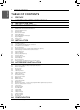
TABLE OF CONTENTS ENGLISH TABLE OF CONTENTS 4 5 12 13 PREFACE IMPORTANT SAFETY INSTRUCTIONS INSTALLATION PART GENERAL INFORMATION 13 14 15 18 19 20 23 29 30 Model Information Model name and related information Parts and Dimensions Control Parts Remote Controller Wiring Diagram Typical Installation Example Cycle Diagram Water cycle 32 INSTALLATION 32 33 34 35 36 42 43 45 45 46 46 47 48 48 49 Transporting the Unit Installation places Seasonal Wind and Cautions in Winter Foundation for Installation E
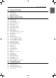
TABLE OF CONTENTS 92 92 93 94 95 96 How to enter service setting Service setting Service Contact Model Information RMC Version lnformation Open Source License 97 INSTALLER SETTING 97 98 100 101 102 103 104 105 106 107 108 109 110 112 114 116 117 118 120 121 122 123 124 125 126 127 128 129 130 131 132 133 134 136 137 138 139 140 141 142 143 144 146 147 148 149 How to enter installer setting Installer setting 3 Minutes Delay Select Temperature Sensor Dry Contact Mode Central Control Address Pump test run
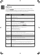
PREFACE ENGLISH PREFACE This installation manual is to present information and guide about understanding, installing, and checking . Your careful reading before installation is highly appreciated to make no mistake and to prevent potential risks. The manual is divided into nine chapters. These chapters are classified according to installation procedure. See the table below to get summarized information. Chapters Contents Chapter 1 • Warning and Caution concerned with safety.
IMPORTANT SAFETY INSTRUCTIONS Read the precautions in this manual carefully before operating the unit. This appliance is filled with flammable refrigerant (R32) This symbol indicates that the Operation Manual should be read carefully. This symbol indicates that a service personnel should be handling this equipment with reference to the Installation Manual. READ ALL INSTRUCTIONS BEFORE USING THE APPLIANCE.
IMPORTANT SAFETY INSTRUCTIONS ENGLISH • Always install a dedicated circuit and breaker. - Improper wiring or installation may cause fire or electric shock • Use the correctly rated breaker or fuse. - There is risk of fire or electric • Do not modify or extend the power cable. - There is risk of fire or electric shock. • Do not install, remove, or reinstall the unit by yourself (customer).
IMPORTANT SAFETY INSTRUCTIONS 7 Operation • Take care to ensure that power cable could not be pulled out or damaged during operation. - There is risk of fire or electric shock. • Do not place anything on the power cable. - There is risk of fire or electric shock. • Do not plug or unplug the power supply plug during operation. - There is risk of fire or electric shock.
IMPORTANT SAFETY INSTRUCTIONS ENGLISH • Do not touch (operate) the unit with wet hands. - There is risk of fire or electric shock. • Do not place a heater or other appliances near the power cable. - There is risk of fire or electric shock. • Do not allow water to run into electric parts. - There is risk of fire, failure of the unit, or electric shock. • Do not store or use flammable gas or combustibles near the unit. - There is risk of fire or failure of unit.
IMPORTANT SAFETY INSTRUCTIONS 9 ENGLISH • Turn the main power on 6 hours ago before the product starting operation. - Otherwise, it may cause compressor damage. • Do not touch electric parts for 10 minutes after main power off. - There is risk of physical injury, electric shock. • The inside heater of product may operate during stop mode. It is intended to protect the product. • Be careful that some part of the control box are hot. - There is risk of physical injury or burns.
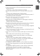
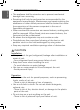
IMPORTANT SAFETY INSTRUCTIONS ENGLISH • The appliance shall be stored so as to prevent mechanical damage from occurring. • Servicing shall only be performed as recommended by the equipment manufacturer. Maintenance and repair requiring the assistance of other skilled personnel shall be carried out under the supervision of the person competent in the use of flammable refrigerants. • When mechanical connectors are reused indoors, sealing parts shall be renewed.
IMPORTANT SAFETY INSTRUCTIONS 11 ENGLISH • Use a firm stool or ladder when cleaning or maintaining the unit. - Be careful and avoid personal injury. • Do not turn on the breaker or power under condition that front panel cabinet, top cover, control box cover are removed or opened. - Otherwise it may cause fire, electric shock, explosion or death. • The appliance shall be disconnected from its power source during service and when replacing parts.
INSTALLATION PART ENGLISH INSTALLATION PART Thank you for choosing LG Electronics Air-to-Water Heat Pump Before starting installation, please make it sure that all parts are found inside the product box.
GENERAL INFORMATION 13 With advanced inverter technology, is suitable for applications like under floor heating, under floor cooling, and hot water generation. By Interfacing to various accessories user can customize the range of the application. In this chapter, general information of is presented to identify the installation procedure. Before beginning installation, read this chapter carefully and find helpful information on installation.
GENERAL INFORMATION ENGLISH Model name and related information Model Name Phase 1Ø 3Ø Capacity Capacity Heating( kW)*1 Cooling( kW)*2 5 kW 5.5 5.5 7 kW 7.0 7.0 9 kW 9.0 9.0 12 kW 12.0 12.0 14 kW 14.0 14.0 16 kW 16.0 16.0 12 kW 12.0 12.0 14 kW 14.0 14.0 16 kW 16.0 16.
GENERAL INFORMATION 15 ENGLISH Parts and Dimensions Product Heating Capacity : 5 kW,7 kW,9 kW UN4 Chassis (unit: mm) 4 4 5 5 9 2 6 7 3 10 8 1 Description No Name Remarks 1 Entering water pipe Male PT 1 inch 2 Leaving water pipe Male PT 1 inch 3 Strainer Filtering and stacking particles inside circulating water 4 Top cover - 5 Control Box PCB and terminal blocks 6 Plate Heat Exchanger Heat exchanger between refrigerant and water 7 Water Pump Circulating the water 8 Pressu
GENERAL INFORMATION ENGLISH Product Heating Capacity : 12 kW,14 kW,16 kW UN3 Chassis (unit: mm) 3D View Side View
GENERAL INFORMATION 17 ENGLISH No Name Remarks 1 Entering water pipe Male PT 1 inch 2 Leaving water pipe Male PT 1 inch 3 Strainer Filtering and stacking particles inside circulating water 4 Top cover - 5 Front Panel - 6 Side Panel - 7 Signal A Network Kit cables 8 Signal B Network Kit cables 9 Signal C - 10 Outdoor Entry Power Cable - 11 Water Pump Circulating the water 12 Plate Heat Exchanger Heat exchanger between refrigerant and water 13 Pressure Gage Indicates
GENERAL INFORMATION ENGLISH Control Parts 1Ø : 12 kW, 14 kW, 16 kW 3Ø : 12 kW, 14 kW, 16 kW 1Ø : 5 kW, 7 kW, 9 kW 2 2 1 1 Description No Name Remark 1 Terminal blocks The terminal blocks allow easy connection of field wiring 2 Main PCB The main PCB(Printed Circuit Board) controls the functioning of the unit
GENERAL INFORMATION 19 ENGLISH Remote Controller Operation display window Back button OK On/Off Button OK Button Up/Down/Left/Right Button Operation display window Operation and Settings status display Back button When you move to the previous stage from the menu’s setting stage Up/down/left/right button When you change the menu’s setting value OK button When you save the menu’s setting value On/Off button When you turn ON/OFF the Unit
GENERAL INFORMATION ENGLISH Wiring Diagram - Refer to the attached wiring diagram.
GENERAL INFORMATION 21 1Ø : 12 kW, 14 kW, 16 kW ENGLISH Wiring Diagram : (Including Field wiring) :
GENERAL INFORMATION ENGLISH Wiring Diagram : (Including Field wiring) : 3Ø : 12 kW, 14 kW, 16 kW
GENERAL INFORMATION 23 ENGLISH Typical Installation Example ! CAUTION If is installed with pre-existing boiler, the boiler and should not be operated together. If entering water temperature of is above 55 °C, the system will stop operation to prevent mechanical damage of the product. For detailed electric wiring and water piping, please contact authorized installer. Some installation scenes are presented for example.
GENERAL INFORMATION ENGLISH CASE 2: Connecting DHW Tank Outdoor Indoor R T M/F Hot water Fan coil unit Floor heating loop Radiator DHW tank City water ! NOTE • DHW tank - It should be equipped with internal electric heater to generate sufficient heat energy in very cold season. - DHW : Domestic Hot Water • 3way valve - Type of 3way valve and specification should be complied with chapter 4 and chapter 7 of installation manual.
GENERAL INFORMATION 25 ENGLISH CASE 3: Connecting Solar thermal system Outdoor Indoor R T M/F Solar heat source Hot water Fan coil unit Floor heating loop Radiator DHW tank City water ! NOTE • DHW tank - It should be equipped with internal electric heater to generate sufficient heat energy in very cold season. - DHW : Domestic Hot Water • Pump - Maximum power consumption of pump should be less than 0.25 kW.
GENERAL INFORMATION ENGLISH CASE 4: Connecting 2nd Circuit [Room A] Main Zone zone (Low Temp.) Outdoor Mix Indoor 2nd circuit temp. sensor R Mix Kit T Floor heating loop Floor heating loop Buffer Tank M/F [Room B] Additional zone (High Temp.) Radiator ! Radiator NOTE • Mix Kit - You can install it when you want to set the temperature of two rooms individually - When heating, Main Zone can not be higher than Add Zone. - When cooling, Main Zone can not be lower than Add Zone.
GENERAL INFORMATION 27 ENGLISH CASE 5: Connecting 3rd Party 3 Way V/V direction Boiler On : Ơ Boiler Off : ȯ Outdoor Indoor R Boiler T Buffer Tank M/F ! Floor heating loop Floor heating loop Floor heating loop NOTE • DHW tank - 3rd Party Boiler - You can control the boiler automatically and manually by comparing the outside temperature and the set temperature. • 3way valve - It is a valve for DHW use.
GENERAL INFORMATION ENGLISH CASE 6 : Connecting backup heater Outdoor Indoor R T Buffer Tank M/F ! Floor heating loop Floor heating Floor heating loop loop NOTE • Backup heater(Accessory) - You can retain sufficient capacity even though ambient temperature will be decreased in winter.
GENERAL INFORMATION 29 ENGLISH Cycle Diagram 1Ø : 12 kW, 14 kW, 16 kW ; 3Ø : 12 kW, 14 kW, 16 kW : Cooling : Heating S6 High Pressure Sensor Pressure Switch S2 Muffler S5 Air Vent Backup Heater Accessory S1 Accumulator S12 S6 Expansion Tank S4 Inv. Comp S8 EEV1 S13 Relief valve Water Out Pressure Gage S9 Air Vent EEV2 IHEX S10 Water [PHE] In Strainer S11 W/Pump Flow Switch EEV3 (Inj.
Ref In Ref Out Unit S10 S9 M/F Magnetic Filter (Mandatory) S11 S12 Basic installation Indoor Unit (Hydro-Kit) EXP/TANK W/PUMP_1 F/S S14 Radiator 2WAY V/V_1 Underfloor Heating 3WAY V/V_1 Fan Coil Unit S15 City Water DHW Tank DHW Tank is Installed (DHW tank is necessary) B/HT Shower W/PUMP_2 S16 SOLAR THERMAL SYSTEM Solar Thermal Componets Solar thermal system is connected (Solar thermal kit is necessary) 3WAY V/V_2 Solor Panel ENGLISH Remote Room Temp.
GENERAL INFORMATION 31 Category Symbol S9 S10 S7 S8 S3 F/S E/HT Meaning Refrigerant temperature sensor (Gas side) Refrigerant temperature sensor (Liquid side) Inlet IHEX temperature sensor Outlet IHEX temperature sensor Compressor-discharge pipe temperature sensor Flow Switch PCB Connector CN_PIPE_OUT CN_PIPE_IN CN_VI_IN CN_VI_OUT CN_DISCHA CN_FLOW1 Electric Heater CN_E/HEAT(A) CN_E/HEAT(B) - Optional accessory (sold separately) - Model : HA**1A E1 - Heating capacity is divided into two level : part
INSTALLATION ENGLISH INSTALLATION Transporting the Unit • When carrying the suspended unit, pass the ropes between legs of base panel under the unit. • Always lift the unit with ropes attached at four points so that impact is not applied to the unit. • Attach the ropes to the unit at an angle Ⓐ of 40° or less. • Use only accessories and parts which are of the designated specification when installing. • Forklift trucks are not available without a palette.
INSTALLATION 33 ENGLISH Installation places - If an awning is built over the unit to prevent direct sunlight or rain exposure, make sure that heat radiation from the condenser is not restricted. - Ensure that the spaces indicated by arrows around front, back and side of the unit. - Do not place animals and plants in the path of the warm air. - Take the Unit weight into account and select a place where noise and vibration are minimum.
INSTALLATION ENGLISH Installation at Seaside ! CAUTION • Unit should not be installed in areas where corrosive gases, such as acid or alkaline gas, are produced. • Do not install the unit where it could be exposed to sea wind (salty wind) directly. It can result corrosion on the unit. Corrosion, particularly on the condenser and evaporator fins, could cause unit malfunc-tion or inefficient performance. • If unit is installed close to the seaside, it should avoid direct exposure to the sea wind.
INSTALLATION 35 • Check the strength and level of the installation ground so that the unit will not cause any operating vibration or noise after installation. • Fix the unit securely by means of the foundation bolts. (Prepare 6sets of M12 foundation bolts, nuts and washers each which are available on the market.) • It is best to screw in the foundation bolts until their length are 20 mm from the foundation surface.
INSTALLATION ENGLISH Electrical Wiring • Follow ordinance of your governmental organization for technical standard related to electrical equipment, wiring regulations and guidance of each electric power company. ! WARNING • Be sure to have authorized electrical engineers do the electric work using special circuits in accordance with regulations and this installation manual. If power supply circuit has a lack of capacity or electric work deficiency, it may cause an electric shock or fire.
INSTALLATION 37 ENGLISH ! CAUTION The power cable connected to the unit should be complied with IEC 60245 or HD 22.4 S4 (This equipment shall be provided with a cable set complying with the national regulation.
INSTALLATION ENGLISH Point for attention regarding quality of the public electric power supply This equipment complies with respectively: - EN/IEC 61000-3-12 (1) provided that the short-circuit power Ssc is greater than or equal to the minimum Ssc value at the interface point between the user's supply and the public system.
INSTALLATION 39 This cable is generally connected between external power source (such as main electric power distribution panel of user's house) and the unit. Before starting wiring, check if wire specification is suitable and read following directions and cautions VERY carefully. ! CAUTION After checking and confirming following conditions, start wiring work. • Secure dedicated power source for the Air-to-Water heat pump.
INSTALLATION ENGLISH Step 2. Connect power cable to main power terminal See below figure for detailed information. When connecting earth cable, the diameter of cable should be refer to the below table. The earth cable is connected to the Control box case where earth symbol is marked. Step 3. Use cable clamps (or cord clamps) to prevent unintended move of power cable. Step 4. Reassemble the side panel to the unit by fastening screws.
INSTALLATION 41 ENGLISH Terminal Block Information Symbols used below pictures are as follows : - L, L1, L2 : Live (220-240 V~) - N : Neutral (220-240 V~) - BR : Brown , WH : White , BL : Blue , BK : Black Terminal Block 1 Water flow switching between under floor heating and DHW tank heating Energizing water pump for solar thermal system 1 2 3 4 5 L L1 N L N WATER PUMP (B) 3WAY VALVE (B) Water flow switching between using solar thermal heating and skipping solar thermal heating 6 7 8 9 1
INSTALLATION ENGLISH Wiring of main power supply and equipment capacity 1. Use a separate unit power and heater power. 2. Bear in mind ambient conditions (ambient temperature,direct sunlight, rain water,etc.) when proceeding with the wiring and connections. 3. The wire size is the minimum value for metal conduit wiring. The power cord size should be 1 rank thicker taking into account the line voltage drops. Make sure the power-supply voltage does not drop more than 10 %. 4.
INSTALLATION 43 ! CAUTION Followings are should be considered before beginning water circuit connection. • Service space should be secured. • Water pipes and connections should be cleaned using water. • Space for installing external water pump should be provided if internal water pump capacity is not enough for installation field. • Never connect electric power while proceeding water charging. Definition of terms are as follow : • Water piping : Installing pipes where water is flowing inside the pipe.
INSTALLATION ENGLISH When the water pipes are connected. It must be tightened the nut with two wrench. Otherwise pipes can be deformed. Water Out Union Water In ! WARNING Installing shut-off valve • While assembling two shut-off valves, pop sound will be heard when valve is open or close by rotating handles. It is normal condition because the sound is due to leakage of charged nitrogen gas inside the valve. The nitrogen gas is applied to secure quality assurance.
INSTALLATION 45 For water charging, please follow below procedures. Step 1. Open all valves of whole water circuit. Supplied water should be charged not only inside the unit, but also in the under floor water circuit, DHW water tank circuit, FCU water circuit, and any other water circuits controlled by the product. Step 2. Connect supply water into drain valve and fill valve located at the side of the shut-off valve. ! CAUTION No water-leakage permitted at the drain and fill valve.
INSTALLATION ENGLISH Water pump Capacity The water pump us variable type which is capable to change flow rate, so it may be required to change default water pump capacity in case of noise by water flow. In most case, however, it is strongly recommended to set capacity as Maximum. ! NOTE • To secure enough water flow rate, do not set water pump capacity as Minimum. It can lead unexpected flow rate error CH14.
INSTALLATION 47 MGQ62321901 : UPML GEO 20 - 105 CHBL (12 kW, 14 kW, 16 kW / UN3 Chassis) MGQ62321902 : UPM3K GEO 20 - 75 CHBL (5 kW, 7 kW, 9 kW / UN4 Chassis) Performance test based on standard ISO 9906 with pre-pressure 2.0 bar and liquid temperature 20 °C. ! WARNING • Selecting a water flowrate outside the curves can cause damage to or malfunction of the unit.
INSTALLATION ENGLISH Water Quality Water quality should be complied with EN 98/83 EC Directives. Detailed water quality condition can be found in EN 98/83 EC Directives. ! CAUTION • If the product is installed at existing hydraulic water loop, it is important to clean hydraulic pipes to remove sludge and scale. • Installing sludge strainer in the water loop is very important to prevent performance degrade. • Chemical treatment to prevent rust should be performed by installer.
INSTALLATION 49 Inside expansion vessel is included which is 8 liter capacity with 1 bar pre-pressure. That means, according to the volume-pressure graph, total water volume of 230 liter is supported as default. If total water volume is changed because of installation condition, the pre-pressure should be adjusted to secure proper operation. - Minimum total water volume is 20 liter. - Pre-pressure is adjusted by the total water volume.
ACCESSORIES INSTALLATION ENGLISH ACCESSORIES INSTALLATION can interface to various accessories to extend its functionality and to improve user convenience. In this chapter, specifications about supported 3rd party accessories and how to connect to is introduced. It is noted that this chapter only deal with 3rd party accessories. For accessories supported by LG Electronics, please refer to installation manual of each accessories.
ACCESSORIES INSTALLATION 51 ENGLISH Accessories supported by 3rd party Companies Item Purpose Specification Solar Heating System To generate auxiliary heating energy for water • Solar collector tank • 3way valve(B) Mix Kit To use 2nd Circuit 3rd Party Boiler To use auxiliary boiler.
ACCESSORIES INSTALLATION ENGLISH Before Installation ! WARNING Followings should be kept before installation • Main power must be turned off during installing 3rd party accessories. • 3rd party accessories should be comply with supported specification. • Proper tools should be chosen for installation. • Never do installation with wet hands. Thermostat Thermostat is generally used to control the product by air temperature.
ACCESSORIES INSTALLATION 53 ENGLISH Direct Sun ray contact area yes no no 1.5 m no General Information The Heat Pump supports following thermostats. Type Mechanical (1) Electrical (2) Power 230 V~ 230 V~ Operating Mode Supported Heating Only (3) Yes Heating / Cooling (4) Yes Heating Only (3) Yes Heating / Cooling (4) Yes (1) There is no electric circuit inside the thermostat and electric power supply to the thermostat is not required.
ACCESSORIES INSTALLATION ENGLISH How to wire thermostat Follow below procedures Step 1 ~ Step 5. Step 1. Uncover front cover of the unit and open the control box. Step 2. Identify the power specification of the thermostat. If it is 220-240 V~, go to Step 3. Step 3. If it is Heating only thermostat, go to step 4. Otherwise, if it is Heating / cooling thermostat, go to step 5. Step 4. Find terminal block and connect wire as below. After connecting, go to step 5.
ACCESSORIES INSTALLATION 55 ENGLISH Final check • DIP switch setting : Set DIP switch No. 8 to ‘ON’. Otherwise, the unit can not recognize the thermostat. • Remote Controller : - ‘Thermostat’ text is displayed on the remote controller. - Button input is prohibited. 2nd Circuit The 2nd circuit is generally used to control the temperature of 2 rooms differently. To use the 2nd Circuit, you need to prepare a separate Mix Kit. The mix kit must be installed in the main zone.
ACCESSORIES INSTALLATION ENGLISH How to Wire 2nd Circuit Follow below procedures Step 1 ~ Step 2. Step 1. Uncover front cover of the unit. Step 2.
ACCESSORIES INSTALLATION 57 NOTE Temperature sensor specification: Type : Thermistor,NTC Resistance at 25 °C : 5 kΩ Minimum operating temperature range : -30 °C~100 °C [Thermistor for 2nd circuit] Sensor Sensor Holder Sensor Connector Follow below procedures step 1 ~ step 4. Step 1. Install sensor connector to outlet pipe of mix kit water pump. (Welding must be performed to connect the sensor connector to the pipe. ) Step 2. Check if the power of the unit is turned off. Step 3.
ACCESSORIES INSTALLATION ENGLISH 3rd Party Boiler The product can be used by connecting an Auxiliary boiler. You can control the boiler automatically and manually by comparing the outside temperature and the set temperature. How to install 3rd party boiler Follow below procedures step 1 ~ step 3. Step 1. Check if the power of the unit is turned off. Step 2. Disassemble front panels and Distinguish terminal block in Indoor PCB. Step 3. Connect Power cable to terminal block (TB_BOILER) fully.
ACCESSORIES INSTALLATION 59 The product can also be linked to 3rd party controller. You can connect external controllers using Modbus protocol except for LG controller. If 3rd party controller is used, LG controller is not applied to AWHP simultaneously. How to install 3rd party controller Follow below procedures step 1 ~ step 4. Step 1. Check if the power of the unit is turned off. Step 2. Disassemble front panels and distinguish control box(Indoor) of the unit. Step 3.
ACCESSORIES INSTALLATION ENGLISH Meter Interface This product can be used by connecting the meter interface module supplied in the field. The meter interface module can communicate with the wired remote controller. The meter interface module lets you know the amount of power generated by the product. How to install Meter Interface [Parts of Meter interface] Meter interface body Follow below procedures step 1 ~ step 4. Step 1. Check if the power of the unit is turned off. Step 2.
ACCESSORIES INSTALLATION 61 The product can communicate and control through the central controller. The following functions can be controlled in the central control linked state (Operation/Stop, Desired temperature, Hot water operation / stop, Warm water temperature, Full lock, Etc) How to Installation PI485 Fix the PI485 PCB as shown in below images.
ACCESSORIES INSTALLATION ENGLISH Remote Controller Installation of Remote Controller • After fixing the remote controller installation plate on the desired location, fix it firmly with the provided screws. - If the installation plate is not flat on the surface, it may result in the controller being twisted and cause a defect. - If there is a mounting box, install the remote controller installation plate using the fixings holes which suit, as in the below diagrams.
ACCESSORIES INSTALLATION 63 Wall Side • Use the connection cables to connect the indoor unit with the remote controller. DC 12 V Red Signal Yellow GND Black Please check if connector is normally connected. Unit side OK Connecting cable • For the following cases, separately purchase and use the cables suitable for the situation. - Do not install the cable over 50 m. (It may cause communication issues.
Indoor PCB CN_REMO 64 ACCESSORIES INSTALLATION ENGLISH Extension Cable Indoor MAIN PCB Wired controller Indoor terminal block RED(12V) YL(SIGNAL) BR(GND) Check whether the connector is connected correctly. Check whether the connector is connected correctly. Cable connection method to use external device 1) Wired remote controller-cable connection method. - In the wired remote controller, connect the part marked in the following figure (J02C, DOPort) to the cable.
ACCESSORIES INSTALLATION 65 To establish DHW circuit, 3way valve and DHW tank kit is required. If solar thermal system is pre-installed at the installation field, solar thermal kit is required to interface solar thermal system – to – DHW tank – to – Installation condition Installing DHW water tank requires following considerations : • DHW water tank should be located at the flat place. • Water quality should be complied with EN 98/83 EC directives.
ACCESSORIES INSTALLATION ENGLISH ! WARNING Installing recirculation pump When is used with DHW tank, it is STRONGLY recommended to install recirculation pump to prevent flooding out cold water at the end of hot water supply and to stabilize the water temperature inside DHW tank - The recirculation pump should be operated when DHW demand is not required. Therefore, external time scheduler to determine when the recirculation pump should turn on and turn off is required.
ACCESSORIES INSTALLATION 67 Step 1. Uncover heater cover of the DHW tank. It is located side of the tank. Step 2. Find terminal block and connect wires as below. Wires are field-supplied item. (L) : Live signal from PCB to Heater (N) : Neutral signal from PCB to Heater ! WARNING Wire specification • Cross-sectional area of the wire should be 6 mm2.
ACCESSORIES INSTALLATION ENGLISH DHW Tank Kit This product can be used by connecting the DHW tank kit in the field. It can be utilized hot water heated by booster heater in DHW tank. How to install DHW tank kit [Parts of DHW Tank Kit] 1 2 3 4 5 6 Tank kit body Sensor Multi harness Temperature sensor for DHW tank is used to control hot water temperature of DHW tank. If sensor will be defective, you can purchase it separately.(Model name : PHRSTA0) Follow below procedures step 1 ~ step 4.
ACCESSORIES INSTALLATION 69 This product can be used by connecting the solar thermal kit in the field. It can be utilized hot water heated by solar thermal system. End-user must be LG AWHP solar thermal kit. How to Install Solar Thermal Kit [Parts of Solar Thermal Kit] Holder sensor Tube Connector Solar Thermal Sensor 12 m(1 EA) Follow below procedures step 1 ~ step 4. Step 1. Install tube connector(it is necessary to reduce or extend diameter of pipe.) the pipe and solar thermal kit. Step 2.
ACCESSORIES INSTALLATION ENGLISH Dry Contact Dry Contact is a solution for automatic control of HVAC system at the owner's best. In simple words, it's a switch which can be used to turn the unit On/Off after getting the signal from external sources. How to install dry contact [Parts of Dry contact] Dry Contact body Cable(for connecting with IDU) Follow below procedures step 1 ~ step 4. CN_CC CN_CC Step 1. Check if the power of the unit is turned off. IndoorIndoor PCB PCB Step 2.
ACCESSORIES INSTALLATION ENGLISH [Setting of Contact Signal Input] LOW MIDDLE HIGH COMM Themal Operation COMM FAN HEAT COOL • For input contact closure only(No power input) Thermostat LG does not supply this section (Field supply) Notes Do not input the voltage signal in "NON VOLT" setting mode otherwise it will cause serious damage LOW MIDDLE HIGH COMM Themal Operation COMM FAN HEAT COOL • For input contact voltage : DC 12 V, 24 V~ Connect separate External voltage of DC 12 V, 24 V~ 71 Thermos
ACCESSORIES INSTALLATION If you require to operate control depending on external digital input(ON/OFF), connect cable to indoor PCB(CN_EXT). Follow below procedures step 1 ~ step 4. Step 1. Check if the power of the unit is turned off. Step 2. Disassemble front panels and distinguish control box(Indoor) of the unit Step 3. Connect the external controller to PCB(CN_EXT) completely. Step 4. Connect the cable and field installation part.
ACCESSORIES INSTALLATION 73 Remote temperature sensor can be installed any place a user wants to detect the temperature. Installation condition Role and constraint while installation of remote air temperature sensor is very similar to that of thermostat. • Distance between the unit and the remote air temperature sensor should be less than 15 m due to length of the connection cable of remote air temperature sensor.
ACCESSORIES INSTALLATION Indoor PCB ENGLISH Fixing screws 60 mm BK WH CN_ROOM Indoor PCB Sensor [fig. 1] [fig. 2] Step 6. Integrate the remote temperature sensor with the screws as the order of arrows. Fixing the Remote Sensor 1 2 ! CAUTION • Choose the place where the average temperature can be measured for the unit operates. • Avoid direct sunlight. • Choose the place where the cooling/heating devices do not affect the remote sensor.
ACCESSORIES INSTALLATION 75 Solar pump can be required to energize water flow when solar thermal system is installed. How to install solar pump Follow below procedures step 1 ~ step 4. Step 1. Check if the power of the unit is turned off. Step 2. Disassemble front panels and distinguish control box(Indoor) of the unit. Step 3. Check if the harness(Black) is inserted fully to the indoor unit PCB (CN_W_PUMP_B). Step 4. Connect the external pump to terminal block 1(4/5).
ACCESSORIES INSTALLATION ENGLISH External pump External pump can be required when the room to take floor heating is too large or not wellinsulated.(potential free) Also, External pump is installed with buffer tank to retain sufficient capacity. How to install external pump Follow below procedures step 1 ~ step 3. Step 1. Check if the power of the unit is turned off. Step 2. Disassemble front panels and distinguish terminal block in Indoor PCB. Step 3.
ACCESSORIES INSTALLATION 77 Wi-fi modem enables remote system operation from smartphone. Available functions include selection of on/off, operation mode, DHW heating, temperature setup and weekly scheduling etc. How to install Wi-fi Modem [Parts of Wi-fi modem] Wi-fi modem body USB Cable Extension Cable Follow below procedures step 1 ~ step 5. Step 1. Check if the power of the unit is turned off. Step 2. Disassemble front panels and distinguish control box(Indoor) of the unit. Step 3.
ACCESSORIES INSTALLATION ENGLISH Smart Grid This product provides SG Ready function for users. It enables to stop internal operation(Heating / DHW) and control target temperature depending on input signal from power provider. How to install smart grid Follow below procedures step 1 ~ step 3. Step 1. Check if the power of the unit is turned off. Step 2. Disassemble front panels and distinguish terminal block in Indoor PCB. Step 3.
ACCESSORIES INSTALLATION 79 2way valve is required to control water flow while cooling operation. Role of 2way valve is to cut off water flow into under floor loop in cooling mode when fan coil unit is equipped for cooling operation. General Information supports following 2way valve. Type Power Operating Mode Supported NO 2-wire (1) 230 V AC Closing water flow Yes Opening water flow Yes NC 2-wire (2) 230 V AC Closing water flow Yes Opening water flow Yes (1) : Normal Open type.
ACCESSORIES INSTALLATION ENGLISH 3Way Valve(A) 3Way Valve(A) is required to operate DHW water tank. Role of 3way valve is flow switching between under floor heating loop and water tank heating loop. Plus, it is required to operate 3rd party boiler. General Information supports following 3way valve.
ACCESSORIES INSTALLATION 81 3way valve(B) is required to operate Solar thermal system. Role of 3way valve is flow switching between open and close mode of the solar circuit. General Information supports following 3way valve. Type SPDT 3-wire (1) Power Operating Mode 220-240 V~ Selecting “Flow A” between “Flow A” and “Flow B” (2) Selecting “Flow B” between “Flow A” and “Flow B” (3) Supported Yes Yes (1) : SPDT = Single Pole Double Throw.
ACCESSORIES INSTALLATION ENGLISH Electric Heater How to Pipe Electric Heater Follow below procedures Step 1 ~ Step 4. Step 1. Uncover the electric heater accessory. Step 2. Check the diameter of pre-installed pipes of unit. Step 3. If the diameter of pre-installed pipes is different from diameter of electric heater accessory kit, it is necessary to reduce or expand pipe's diameter. Step 4. Connect the pipes. The inlet pipe of electric heater accessory must be connected to outlet of the unit.
ACCESSORIES INSTALLATION 83 Follow below procedures Step 1 ~ Step 4. Step 1. Uncover the electric heater accessory. Step 2. Find the terminal block and connect wires. Refer to the installation manual of the electric heater. (Wires are field-supplied item.) Step 3. Connect terminal block ports unit and electric heater accessory.
ACCESSORIES INSTALLATION ENGLISH How to Install 3way Valve for Backup Heater Bypass Follow below procedures Step 1 ~ Step 2. Step 1. Uncover front cover of the unit. Step 2. Find terminal block and connect wire as below. When Tightening the connect wire on terminal block, Be careful to prevent a shock or injury. (230 VAC) 2WAY VALVE (B) 18 19 20 BR WH BL L L1 N (NO) (NC) (N) 3way valve ! WARNING • When type of 2way valve is NO type, 3way valve should select Flow A(bypass).
ACCESSORIES INSTALLATION 85 ENGLISH Final check No. Check point Description Connection of Water Inlet/Outlet - Check if the shut-off valves should be assembled with Water inlet and outlet pipe of the unit - Check the location of the water inlet/outlet water pipe Hydraulic pressure - Check the pressure of supplying water by using pressure gage inside the unit - Pressure of Supplying water should be Under 3.
ACCESSORIES INSTALLATION As is designed to satisfy various installation environment, it is important to set up system correctly. If not configured correctly, improper operation or degrade of performance can be expected. DIP Switch Setting ! CAUTION Turn off electric power supply before setting DIP switch • Whenever adjusting DIP switch, turn off electric power supply to avoid electric shock.
CONFIGURATION 87 ENGLISH DIP Switch Information Option Switch 2 Description Setting Role when central controller is equipped 1 As Master 1 As Slave 2 Accessory installation information 3 2 3 2 3 2 3 Default 1 Unit + Outdoor unit is installed Unit + Outdoor unit + DHW tank is installed Unit + Outdoor unit + DHW tank + Solar thermal system is installed 2 3 Reserved 4 Heating Only 4 Heating & Cooling 5 Always Cycle 4 Flow Switch Detection 5 While water pump is on 5 Electric hea
CONFIGURATION ENGLISH Description Option Switch 1 Setting Default Description Setting Default 1 As Master 1 As Slave 2 Common 3rd party 2 SIEMENS 1 MODBUS MODBUS Function 2 Reserved 3 3 4 4 Reserved Reserved 3 Reserved 4 Option Switch 3 Description Setting Description Remote Air Sensor 1 Remote sensor is not installed Setting 1 Remote sensor is installed 2 Antifreeze mode not use 2 Antifreeze mode ANTIFREEZE Default Default 1 2 Reserved 3 3 4 4 Reserved Rese
CONFIGURATION 89 ENGLISH Outdoor PCB General Information ON SW2 1 2 3 4 5 6 7 8 9 10 OFF OFF is selected ON is selected DIP Switch Information Description Setting Default 2 Normal Low Noise Mode 2 Limited Low Noise Mode 3 Max Mode 3 Peak Control : To limit maximum current (Power saving) Low Noise Mode 2 Peak Control 3 h Only DIP-switch no. 2 and no.3 has a function. Others have no function.
CONFIGURATION ENGLISH ! NOTE Emergency Operation • Definition of terms - Trouble : a problem which can stop system operation, and can be resumed temporally under limited operation without certificated professional's assist. - Error : problem which can stop system operation, and can be resumed ONLY after certificated professional's check. - Emergency mode : temporary heating operation while system met Trouble.
CONFIGURATION 91 NOTE • Duplicated trouble : Option trouble with slight or heavy trouble - If option trouble is occurred with slight (or heavy) trouble at the same time, the system puts higher priority to slight (or heavy) trouble and operates as if slight (or heavy) trouble is occurred. - Therefore, sometimes DHW heating can be impossible in emergency operation mode. When DHW is not warming up while emergency operation, please check if DHW sensor and related wiring are all Ok.
CONFIGURATION ENGLISH SERVICE SETTING How to enter service setting To enter the menu displayed at the bottom, you need to enter the service setting menu as follows. • In the menu screen, press [<,>(left/right)] button to select the setting category, and press [OK] button to move to the setting list. • In the setting list, select the service setting category, and press [OK] button to move to the service setting list. OK Service setting • You can set the product service functions.
SERVICE SETTING 93 Check and input the service center phone number that you can call when there is service issue. • In the service setting list, select the service contact point and press [OK] button to move to the detail screen. • While “edit” button is selected, press [OK] button to move to the edit screen, change it, and press [OK] button to change the service contact point.
SERVICE SETTING ENGLISH Model Information Check product and capacity information to which the remote controller is connected. • In the service setting list, select model information category, and press [OK] button to move to the detail screen. • The unit capacity - 1 kWh = 1 kBtu * 0.29307 kWh is the result calculated based on Btu, There may be a small difference between calculated and actual capacity. Ex) If the unit capacity is 18 kBtu, it is displayed as 5 kWh.
SERVICE SETTING 95 View the remote controller software version.
SERVICE SETTING ENGLISH Open Source License View the remote controller’s open source license. • In the service setting list, select the open source license category, and press [OK] button to move to the detail screen.
INSTALLER SETTING 97 ENGLISH INSTALLER SETTING How to enter installer setting ! CAUTION The installer setting mode is the mode to set the remote controller’s detail function. If the installer setting mode is incorrectly set, it may cause product failure, user’s injury, or property damage.
INSTALLER SETTING ENGLISH Installer setting • You can set the product user functions. • Some functions may not be displayed/operated in some product types. Function 3 Minutes Delay Description Factory use only Select Temperature Sensor Selection for setting temperature as air temperature or leaving water temperature or air+leaving water temperature Dry Contact Mode setting Dry contact function is the function that can be used only when the dry contact devices is separately purchased and installed.
INSTALLER SETTING 99 Description TH on/off Variable, cooling Water setting Cooling Water Outlet Temperature TH On / Off Type Heating temp. setting At the leaving water control in heating mode, the control reference water temperature position setting Cooling temp.
INSTALLER SETTING ENGLISH 3 Minutes Delay Temporarily eliminates the 3-minute delay function of the outdoor unit Comp - Factory use only • In the installer setting list, select 3 Minutes Delay category, and press [OK] button to move to the detail screen.
INSTALLER SETTING 101 The product can be operated according to air temperature or leaving water temperature. The selection for setting temperature as air temperature or leaving water temperature is determined. • In the installer setting list, Select Temperature Sensor category, and press [OK] button to move to the detail screen.
INSTALLER SETTING ENGLISH Dry Contact Mode Dry contact function is the function that can be used only when the dry contact devices is separately purchased and installed. • Change setting values using [<,>(left/right)] button. Value Auto manual ! NOTE For dry contact mode related detail functions, refer to the individual dry contact manual. What is dry contact? It means the contact point signal input when the hotel card key, human body detection sensor, etc. are interfacing with the air conditioner.
INSTALLER SETTING 103 When connecting the central control, set the central control address of the unit. • In the installer setting list, select Central Control Address category, and press [OK] button to move to the detail screen. OK ! NOTE Enter address code as hexadecimal value Front: Central Control Gr. No.
INSTALLER SETTING ENGLISH Pump test run The pump test run is the function to test run by operating the water pump. This function can be used for air vents / flow sensors and others. • In the installer setting list, Pump Test run category, and press [OK] button to move to the detail screen.
INSTALLER SETTING 105 Determine cooling setting temperature range when air temperature is selected as setting temperature. • In the installer setting list, select Air cooling set temp category, and press [OK] button to move to the detail screen. OK Value Default Range Max. 30 30~24 Min. 18 22~16 * Upper / lower limit / default value is in °C ! NOTE Only available when remote air temperature sensor is connected. • Accessory PQRSTA0 should be installed.
INSTALLER SETTING ENGLISH Water cooling set temp Determine cooling setting temperature range when leaving water temperature is selected as setting temperature. • In the installer setting list, select water cooling set temp category, and press [OK] button to move to the detail screen. OK Value Max. Min.
INSTALLER SETTING 107 Determine heating setting temperature range when air temperature is selected as setting temperature • In the installer setting list, select Air heating set temp. category, and press [OK] button to move to the detail screen. OK Value Default Range Max. 30 30~24 Min. 16 22~16 * Upper / lower limit / default value is in °C ! CAUTION Only available when remote air temperature sensor is connected. • Accessory PQRSTA0 should be installed.
INSTALLER SETTING ENGLISH Water heating set temp Determine heating setting temperature range when leaving water temperature is selected as setting temperature • In the installer setting list, select Water heating set temp. category, and press [OK] button to move to the detail screen. OK Value Default Range Max. 65 65~35 Min.
INSTALLER SETTING 109 Determine heating setting temperature range when DHW temperature is selected as setting temperature • In the installer setting list, select DHW set temp. category, and press [OK] button to move to the detail screen. OK Value Range Max. 80~50 Min.
INSTALLER SETTING ENGLISH Screed drying This function is a unique feature of AWHP that, when AWHP is installed in a new concrete structure, controls the specific temperature floor heating out temperature for a certain period of time to cure the floor cement. • In the installer setting list, select Screed drying category, and press [OK] button to move to the detail screen. OK How to display Main Screen - Displays 'Screed drying' on the desired temperature display.
INSTALLER SETTING 111 ENGLISH ! NOTE Leaving Water target temperature °C • During Screed drying operation, button input except for installer function and temperature display is restricted. • When the power is applied again after a power outage during product operation, the product operation state before power failure is remembered and the product is automatically operated. • Screed drying operation stops when an error occurs / When error is cleared, restart cement Screed drying.
INSTALLER SETTING ENGLISH Heater on temperature Depending on local climatic conditions, it is necessary to change the temperature condition in which electric heater turns on / off. • In the installer setting list, Heater on temperature category, and press [OK] button to move to the detail screen.
INSTALLER SETTING 113 NOTE • Heater on temperature Using Half capacity of electric heater : when DIP Switch No. 6 and 7 is set as ‘OFF-ON’ : - Example : If Heater on temperature is set as ‘-1’ and DIP switch No 6. and 7 is set as ‘OFF-ON’, then half capacity of electric heater will start operation when outdoor air temperature is below -1 °C and current leaving water temperature or room air temperature is much belower than target leaving water temperature or target room air temperature.
INSTALLER SETTING ENGLISH Water supply off temp. during cooling Determine leaving water temperature when the unit is turned off. This function is used for preventing condensation on the floor in cooling mode • In the installer setting list, select Water supply off temp. during cooling category, and press [OK] button to move to the detail screen.
INSTALLER SETTING 115 ! CAUTION FCU Installation • If FCU is used, related 2way valve should be installed and connected to the unit PCB. • If FCU is set as ‘Not use’ but FCU or 2way valve is NOT installed, the unit can do abnormal operation. ENGLISH - Stop temp. : cut-off temperature. Stop temp. is valid when FCU is installed. - FCU : determines if FCU is installed or not. - Example : If Stop temp.
INSTALLER SETTING ENGLISH Tank disinfection setting 1, 2 • Disinfection operation is special DHW tank operation mode to kill and to prevent growth of viruses inside the tank. - Disinfection active : Selecting enable or disable of disinfection operation. - Start date : Determining the date when the disinfection mode is running. - Start time : Determining the time when the disinfection mode is running. - Max temp. : Target temperature of disinfection mode. - Duration time : Duration of disinfection mode.
INSTALLER SETTING 117 • In the installer setting list, select tank setting 1 category, and press [OK] button to move to the detail screen.
INSTALLER SETTING ENGLISH Tank setting 2 • In the installer setting list, select tank setting 2 category, and press [OK] button to move to the detail screen.
INSTALLER SETTING 119 - Hysteresis : temperature gap from target DHW temperature. This value is required to frequent On and Off of water tank heater. - Heating priority : Determining heating demand priority between DHW tank heating and under floor heating. - Example : If user’s target temperature is set as ’70’ and Hysteresis is set as ‘3’, then the water tank heater will be turned off when the water temperature is above 73 °C.
INSTALLER SETTING ENGLISH Heater priority - Heater priority : determine electric heater and DHW tank heater on and off. - Example : If Heater priority is set as ‘Main+Boost heater ON’, then electric heater and DHW tank heater are on and off according to control logic. If Heater priority is set as ‘Boost heater only ON’, then electric heater is never turned on and only DHW tank heater is on and off according to control logic.
INSTALLER SETTING 121 Determine following time duration : operation time of DHW tank heating, stop time of DHW tank heating, and delay time of DHW tank heater operating. - Active time : This time duration defines how long time DHW tank heating can be continued. - Stop time : This time duration defines how long time DHW tank heating can be stopped. It is also regarded as time gap between DHW tank heating cycle.
INSTALLER SETTING ENGLISH TH on/off Variable, heating air It is a function to adjust the heating air temperature Thermal On / Off temperature according to the field environment in preparation for heating or heating claim. • You can set the following setting values using [<,>(left/right)] button. Value Description TH On TH Off Type0 -0.5 °C 1.
INSTALLER SETTING 123 It is a function to adjust the heating water temperature Thermal On / Off temperature according to the field environment in preparation for heating or heating claim. • You can set the following setting values using [<,>(left/right)] button.
INSTALLER SETTING ENGLISH TH on/off Variable, cooling air It is a function to adjust the cooling air temperature Thermal On / Off temperature according to the field environment in preparation for cooling or cooling claim. • You can set the following setting values using [<,>(left/right)] button. Value Description TH On TH Off Type0 0.5 °C -0.
INSTALLER SETTING 125 It is a function to adjust the cooling water temperature Thermal On / Off temperature according to the field environment in preparation for cooling or cooling claim. • You can set the following setting values using [<,>(left/right)] button. Value Description TH On TH Off Type0 0.5 °C -0.
INSTALLER SETTING ENGLISH Heating temp.
INSTALLER SETTING 127 • At the leaving water control in cooling mode, the control reference water temperature position setting - If the air / leaving water temperature selection setting is set to leaving water temperature • Change setting values using [<,>(left/right)] button Value Outlet (Default) Inlet ENGLISH Cooling temp.
INSTALLER SETTING ENGLISH Pump setting in heating • It is a function to help the water pump's mechanical life by putting the water pump's rest time • Installer setting function to set water pump operation / delay time option in heating mode • In the installer setting list, select Pump setting in heating category, and press [OK] button to move to the detail screen.
INSTALLER SETTING 129 • It is a function to help the water pump's mechanical life by putting the water pump's rest time • installer setting function to set water pump operation / delay time option in cooling mode • In the installer setting list, select Pump setting in cooling category, and press [OK] button to move to the detail screen. OK Type Time setting Operation continue On 1 Minute ~ 60 minutes - Off 1 Minute ~ 60 minutes - ENGLISH Pump setting.
INSTALLER SETTING ENGLISH Forced operation • If the product is not used for a long time, the product will be forced to operate to prevent pump failure and PHEX freezing • Water pump off After 20 consecutive hours, disable / enable the logic that drives the water pump by itself • In the installer setting list, select Forced operation category, and press [OK] button to move to the detail screen OK Type Use Not use Oper. Cycle 20 minutes ~ 60 minutes - Oper.
INSTALLER SETTING 131 It is the function to set the usage of the unit’s CN_CC port.
INSTALLER SETTING ENGLISH Pump Capacity It is a function to enable installer to control Pump capacity application model. • In the installer setting list, select Pump Capacity category, and press [OK] button to move to the detail screen.
INSTALLER SETTING 133 It is the function to enable / disable the SG Ready function and to set the reference value at SG2 step. • In the installer setting list, select Smart Grid(SG) category, and press [OK] button to move to the detail screen.
INSTALLER SETTING ENGLISH Seasonal auto temp It is the function to set the operation reference value in Seasonal Auto mode. • In the installer setting list, select Seasonal auto temp category, and press [OK] button to move to the detail screen.
INSTALLER SETTING 135 Auto-Adjustable Target Temp. Room Air Temp.( °C) Leaving Water Temp. Outdoor Air Temp.
INSTALLER SETTING ENGLISH Modbus Address It is function to set the address of the Modbus device that is externally linked to the product. Modbus address setting function is available from indoor unit. • In the installer setting list, select Modbus Address , and press [OK] button to move to the detail screen. OK ! NOTE To use this function, switch No.1 of option switch 1 must be turned ON.
INSTALLER SETTING 137 It is a function to control external input and output according to DI type set by customer using CN-EXT Port. • In the installer setting list, select CN-EXT Port category, and press [OK] button to move to the detail screen.
INSTALLER SETTING ENGLISH Anti-freezing Temperature Anti-freeze temperature setting is available in installer mode. It prevents frostbite from happening In the range of -25 to -5 degree celsius. • Change setting values using [<, >(left/right)] button ! NOTE To use this function, the antifreeze short pin must be open and switch No.2 in Option SW 3 must be on.
INSTALLER SETTING 139 Function to set whether or not to use a installed 2nd circuit function using mixing kit. You can set valve closing time[seconds] and hysteresis temperature[ °C] on screen by yourself. Activating this function, It allows 2 zones(Room1, Room2) temperature to be controlled, separately. - In case of heating, the temperature of Room1 can not be set higher than Room2 temperature. - In case of cooling, the temperature of Room1 can not be set lower than Room2 temperature.
INSTALLER SETTING ENGLISH Use External Pump This function can be set to control the external water pump. • In the installer setting list, select Use External Pump category, and press [OK] button to move to the detail screen.
INSTALLER SETTING 141 This function is to configure the 3rd party boiler to be controlled. If the status of this function is “Use”, you can choose control mode of boiler, Auto or Manual. If the mode of this function is set to “Manual”, you can set temperature of the boiler and hysteresis, respectively. External boiler ON condition : - If outdoor temperature ≤ external boiler operation temperature value (installer setting), turn off the indoor unit and operate the external boiler.
INSTALLER SETTING ENGLISH Meter Interface It is the function that can check the status of energy and power on screen. It collects and calculates power or calorie data to create data for energy monitoring and energy warning alarm pop-ups. This function can be activated in installer mode. OK There are 2 options, modbus address and unit, in this function. Activating the modbus address option, you choose one address(B0 or B1) or don’t use. Then, you set the port and specification in range of 0000.0~9999.
INSTALLER SETTING 143 Pump Prerun operates to ensure sufficient flow before the compressor is operated. This is a function that allows heat exchange to work smoothly. Pump Overrun is a function to prevent water pump failure and to help mechanical life.
INSTALLER SETTING ENGLISH Solar Thermal System It is function to set operation reference value in Solar Thermal System. In the installer setting list, select Solar thermal system category, and press [OK] button to move to the detail screen. ! NOTE To use this function, switch No.2 of option switch 2 must be turned ON and No.3 of option switch 2 must be turned OFF.
INSTALLER SETTING 145 Function Solar collector set temp DHW set temp TH on/off Variable, solar Boost Heater Solar pump flush schedule Solar pump test run Solar pump flush setting Value Range Default Min 5 °C ~ 50 °C 10 °C Max 60 °C~105 °C 95 °C Max 20 °C~90 °C 80 °C 8 °C Temp On 3 °C ~ 40 °C Temp Off 1 °C ~ 20 °C 2 °C Boost Heater Enable/Disable Enable On/OFF On/Off On Start Hour, Start Minute 00:00 ~ 24:00 6:00 End Hour, End Minute 00:00 ~ 24:00 18:00 Pump test Run Start/Sto
INSTALLER SETTING ENGLISH Data logging It is the function to set the operation reference value in Seasonal Auto mode. • In the installer setting list, select Data logging category, and press [OK] button to move to the detail screen.
INSTALLER SETTING 147 It is the function to initialize (0000) when you forgot the password set in the remote controller. • In the installer setting list, select the password initialization setting category, and press [OK] button to move to the detail screen. • When you press “initialization” button, a popup screen appears, and when you press “check” button, password initialization starts, and the user password is changed to 0000.
INSTALLER SETTING ENGLISH Power Supply Blockage (SG Ready) The heat pump operated automatically by the power supply status signals from power supply companies. This function can respond to European countries’ special tariff for heat pump using on a smart grid. Power Supply Status Operating Mode 0:0 [Normal Operation] The heat pump works at maximum efficiency. 4 modes depending on power supply status 1:0 [Switch-off command, Utility lock] Deactivates the heat pump to avoid peak load.
INSTALLER SETTING 149 ENGLISH Overview settings Menu Structure Menu Sub function Service Contact .......................................................93 Model information .......................................................94 RMC Version Information .......................................................95 Open Source License .......................................................96 3 Minutes Delay .....................................................100 Select Temperature Sensor ..........
INSTALLER SETTING ENGLISH TH on/off Variable, cooling air .....................................................124 TH on/off Variable, cooling water .....................................................125 Heating temp. setting .....................................................126 Cooling temp. setting .....................................................127 Pump setting in heating .....................................................128 Pump setting. in cooling .............................
COMMISSIONING 151 If everything is going well until now, it is time to start the operation and to take advantages of . Before starting operation, pre-check points are described in this chapter. Some comments about maintenance and how to do troubleshooting are presented.
COMMISSIONING ENGLISH To assure best performance of , it is required to perform periodical check and maintenance. It is recommended to proceed following check list for once a year. ! CAUTION Turn off the power before proceeding maintenance No Category Item 1 Water pressure 2 Water Strainer(Water filter) • Close the shut-off valves and disassemble strainer. Then wash the strainer to make it clean. • While disassembling the strainer, be careful for water flood out.
COMMISSIONING 153 START Operate the unit in heating mode. Does Test operation start? No Check whether the power cable and communication cable are completely connected Yes Is cold water discharged for more than 3 minutes ? Yes No Is there any temperature difference between intake and discharged water? No * Check the load (In/Out Temp.) * Check pipe length and amount of refrigerant * Check for abnormal sound in outdoor unit (comp.
COMMISSIONING ENGLISH Vacuum & Charge of Refrigerant By default, the product was charged of refrigerant. Vacuum and refrigerant charge, If there is leak refrigerant. 1. Vacuum To work of vacuum action. when the leak of refrigerant. SVC Port Manifold gage Manifold valve Pressure gage Open Lo Hi Close Vacuum pump (0.
COMMISSIONING 155 Gage Pressure Absolute Pressure Torr Micron mmHg Pa Unit Standard atmospheric pressure Perfect vacuum Pa Pa Torr Micron mmHg Pa 0 1.033 760 760000 0 1013.33 -1.033 0 0 0 760 0 2. Charge of refrigerant You should be charged after vacuum. You can see amount of refrigerant at quality label. Please to charge at cooling mode when there is not full charging.
COMMISSIONING ENGLISH Refrigerant cylinder Refrigerant cylinder 3.
COMMISSIONING 157 If operates not properly or it does not start operation, please check following list. ! CAUTION Turn off the power before proceeding troubleshooting Troubleshooting for Problem while Operation No 1 Problem Heating or Cooling is not satisfactory. Reason • Setting target temperature is not proper. • Set target temperature correctly. • Check if temperature is water-based or air-based. See "Remote sensor active' and 'Temp. sensor selection' in Chapter6.
COMMISSIONING ENGLISH Troubleshooting for Error Code Code No.
COMMISSIONING 159 21 Title DC PEAK (IPM Fault) Cause of error Check point & Normal condition • Instant over current • Over Rated current • Poor insulation of IPM • An instant over current in the U,V,W phase - Comp lock - The abnormal connection of U,V,W • Over load condition - Overcharging of refrigerant Pipe length. Outdoor Fan is stop • Poor insulation of compressor 1. Malfunction of Compressor 2. Blocking of Pipe 3. Low Voltage Input 4. Refrigerant, Pipe length, Blocked... 22 Max.
COMMISSIONING ENGLISH Display code 41 Title Problem in D-pipe temperature sensor Cause of error Check point & Normal condition • Open / Short • Soldered poorly • Internal circuit error 1. Bad connection of thermistor connector 2. Defect of thermistor connector (Open/Short) 3.
COMMISSIONING 161 Title Cause of error Check point & Normal condition 67 Fan lock error Fan RPM is less than 10 for 5 seconds from start-up operation. Fan RPM is less than 40 in operation except for start-up operation 1. Fan motor damage 2. Assembly condition abnormal 3. Jammed fan by surroundings 114 Problem in Vapor injection inlet temperature sensor • Open (Below -48.7 °C)/ Short(Over 96.2 °C) • Soldered poorly • Internal circuit error 1. Bad connection of thermistor connector 2.
ENGLISH
[Representative] LG Electronics Inc. EU Representative : LG Electronics European Shared Service Center B.V. Krijgsman 1, 1186 DM Amstelveen, The Netherlands [Manufacturer] LG Electronics Inc.