
Installation guide


89
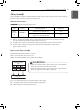
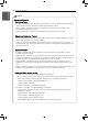
CONFIGURATION
ENGLISH
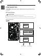
Outdoor PCB General Information
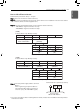
OFF is selected ON is selected
OFF
ON
SW2
1 2 3 4 5 6 7 8 9 10
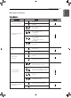
Description Setting Default
Peak Control
Low Noise Mode
3
3
Max Mode
2
Limited Low Noise Mode
2
Normal Low Noise Mode
Peak Control : To limit maximum
current (Power saving)
3
2
DIP Switch Information
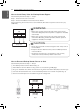
NOTE
!
* Input current value can be limited by DIP Switch operation.
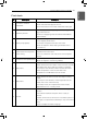
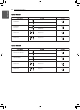
Capacity Mode
Max Mode
Running Current(A)
Peak Control Mode
Running Current(A)
1Ø 5,7,9 kW
Cooling 23 17
Heating 23 17
1Ø 12,14,16 kW
Cooling 35 25
Heating 35 27
3Ø 12,14,16 kW
Cooling 15 10
Heating 15 12
h Only DIP-switch no. 2 and no.3 has a function. Others have no function.
h When setting the limited low noise mode, Mode can be exited to secure capacity after
operating for a certain time.