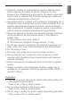
ENGLISH ITALIANO ESPAÑOL FRANÇAIS INSTALLATION MANUAL DEUTSCH AIR-TO-WATER HEAT PUMP ΕΛΛΗΝΙΚΆ ČEŠTINA POLSKI Original instruction www.lg.com Copyright © 2017 - 2018 LG Electronics Inc. All Rights Reserved. LIMBA ROMÂNĂ MFL68681810 Rev.04_062218 NEDERLANDS Please read this installation manual completely before installing the product. Installation work must be performed in accordance with the national wiring standards by authorized personnel only.
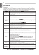
TABLE OF CONTENTS ENGLISH TABLE OF CONTENTS 4 5 12 13 PREFACE IMPORTANT SAFETY INSTRUCTIONS INSTALLATION PART GENERAL INFORMATION 13 14 15 20 21 24 29 30 Model Information Model name and related information Parts and Dimensions Control Parts Control Panel Typical Installation Example Cycle Diagram Water cycle 32 INSTALLATION OF OUTDOOR UNIT 32 32 33 33 Conditions where Outdoor Unit is Installed Drill a Hole in the Wall Installation at Seaside Seasonal wind and cautions in winter 34 INSTALLATION O
TABLE OF CONTENTS How to enter service setting Service setting Service contact Model information RMC version lnformation Open source license 88 INSTALLER SETTING 88 89 91 92 93 94 95 96 97 98 99 100 101 103 105 107 108 109 111 112 113 114 115 116 117 118 119 120 121 122 123 125 126 127 128 129 130 131 132 133 134 135 How to enter installer setting Installer setting 3 Minutes Delay Select Temperature Sensor Dry Contact Mode Central Control Address Pump test run Air cooling set temp.
PREFACE ENGLISH PREFACE This installation manual is to present information and guide about understanding, installing, and checking . Your careful reading before installation is highly appreciated to make no mistake and to prevent potential risks. The manual is divided into nine chapters. These chapters are classified according to installation procedure. See the table below to get summarized information. Chapters Contents Chapter 1 • Warning and Caution concerned with safety.
IMPORTANT SAFETY INSTRUCTIONS 5 Read the precautions in this manual carefully before operating the unit. This symbol indicates that the Operation Manual should be read carefully. This symbol indicates that a service personnel should be handling this equipment with reference to the Installation Manual. READ ALL INSTRUCTIONS BEFORE USING THE APPLIANCE.
IMPORTANT SAFETY INSTRUCTIONS ENGLISH • Always install a dedicated circuit and breaker. - Improper wiring or installation may cause fire or electric shock • Use the correctly rated breaker or fuse. - There is risk of fire or electric • Do not modify or extend the power cable. - There is risk of fire or electric shock. • Do not install, remove, or reinstall the unit by yourself (customer).
IMPORTANT SAFETY INSTRUCTIONS 7 Operation • Take care to ensure that power cable could not be pulled out or damaged during operation. - There is risk of fire or electric shock. • Do not place anything on the power cable. - There is risk of fire or electric shock. • Do not plug or unplug the power supply plug during operation. - There is risk of fire or electric shock.
IMPORTANT SAFETY INSTRUCTIONS ENGLISH • Do not touch (operate) the unit with wet hands. - There is risk of fire or electric shock. • Do not place a heater or other appliances near the power cable. - There is risk of fire or electric shock. • Do not allow water to run into electric parts. - There is risk of fire, failure of the unit, or electric shock. • Do not store or use flammable gas or combustibles near the unit. - There is risk of fire or failure of unit.
IMPORTANT SAFETY INSTRUCTIONS 9 ENGLISH • Turn the main power on 6 hours ago before the product starting operation. - Otherwise, it may cause compressor damage. • Do not touch electric parts for 10 minutes after main power off. - There is risk of physical injury, electric shock. • The inside heater of product may operate during stop mode. It is intended to protect the product. • Be careful that some part of the control box are hot. - There is risk of physical injury or burns.
IMPORTANT SAFETY INSTRUCTIONS ENGLISH • The appliance shall be stored so as to prevent mechanical damage from occurring. • Servicing shall only be performed as recommended by the equipment manufacturer. Maintenance and repair requiring the assistance of other skilled personnel shall be carried out under the supervision of the person competent in the use of flammable refrigerants. • When mechanical connectors are reused indoors, sealing parts shall be renewed.
IMPORTANT SAFETY INSTRUCTIONS 11 ENGLISH • Use a firm stool or ladder when cleaning or maintaining the unit. - Be careful and avoid personal injury. • Do not turn on the breaker or power under condition that front panel cabinet, top cover, control box cover are removed or opened. - Otherwise it may cause fire, electric shock, explosion or death. • The appliance shall be disconnected from its power source during service and when replacing parts.
INSTALLATION PART ENGLISH INSTALLATION PART Thank you for choosing LG Electronics Air-to-Water Heat Pump Before starting installation, please make it sure that all parts are found inside the product box.
GENERAL INFORMATION 13 With advanced inverter technology, is suitable for applications like under floor heating, under floor cooling, and hot water generation. By Interfacing to various accessories user can customize the range of the application. In this chapter, general information of is presented to identify the installation procedure. Before beginning installation, read this chapter carefully and find helpful information on installation.
GENERAL INFORMATION ENGLISH Model name and related information Model Name Outdoor Unit Phase 1Ø Capacity Indoor Unit Phase Capacity Built-In Electric Heater(kW) Power Source (Electric Heater) Heating Cooling (kW)*1 (kW)*2 5 kW 5.0 5.0 7 kW 7.0 7.0 9 kW 9.0 9.0 12.0 10.4 14.0 12.0 16.0 13.0 12.0 10.4 14.0 12.0 16.0 13.
GENERAL INFORMATION 15 ENGLISH Parts and Dimensions Indoor unit(External) (unit : mm) 315 315 850 490 490 Description No Name Remark 1 Control Panel Built-in Remote Controller
GENERAL INFORMATION (unit : mm) 484 13 9 289.6 12 10 7 8 6 14 15 5 1 2 16 16 4 3 84.5 116 123 484 76 41 36.9 46.4 63.4 847.
GENERAL INFORMATION No Name Remark 1 Leaving Water Pipe Male PT 1 inch 2 Entering Water Pipe Male PT 1 inch 3 Refrigerant Pipe Ø9.52mm 4 Refrigerant Pipe Ø15.88mm 5 Water Pump Max Head 9.5 / 7 / 6 m 6 Safety Valve Open at water pressure 3 bar 7 Control Box PCB and terminal blocks 8 Thermal switch Cut-off power input to electric heater at 90 °C (manual return at 55C) 9 Flow Switch Minimum operation range at 15 LPM.
GENERAL INFORMATION Product Heating Capacity : 12kW,14kW,16kW U3 Chassis (unit : mm) Supporter 490 ENGLISH Outdoor unit(External) Description No Name 1 Liquid-side Service Valve 2 Gas-side Service Valve 3 Air discharge Grill
GENERAL INFORMATION 19 ENGLISH Product Heating Capacity : 5kW,7kW,9kW U4 Chassis (unit : mm) Supporter Description No Name 1 Liquid-side Service Valve 2 Gas-side Service Valve 3 Air discharge Grill
GENERAL INFORMATION ENGLISH Control Parts Control Box : Indoor Unit 1Ø Electric Heater Model 3Ø Electric Heater Model Description No Name Remark 1 Terminal blocks The terminal blocks allow easy connection of field wiring 2 Unit ELB The ELB protects the unit against overload or short circuit 3 Water tank heater ELB(optional) The ELB protects the water tank heater in sanitary water tank against overload or short circuit 4 Magnetic switch 5 Main PCB The main PCB(Printed Circuit Board) con
GENERAL INFORMATION 21 ENGLISH Control Panel Operation display window Back button OK On/Off Button OK Button Up/Down/Left/Right Button Operation display window Operation and Settings status display Back button When you move to the previous stage from the menu’s setting stage Up/down/left/right button When you change the menu’s setting value OK button When you save the menu’s setting value On/Off button When you turn ON/OFF the air conditioner Wiring Diagram : Indoor Unit - Refer to the wiri
GENERAL INFORMATION ENGLISH Wiring Diagram : Indoor and Outdoor Unit(Including Field wiring) (Indoor : Electric Heater 1Ø, Outdoor : 1Ø)
GENERAL INFORMATION 23 ENGLISH Wiring Diagram : Indoor and Outdoor Unit(Including Field wiring) (Indoor : Electric Heater 3Ø, Outdoor : 3Ø)
GENERAL INFORMATION ENGLISH Typical Installation Example ! CAUTION If is installed with pre-existing boiler, the boiler and should not be operated together. If entering water temperature of is above 55°C, the system will stop operation to prevent mechanical damage of the product. For detailed electric wiring and water piping, please contact authorized installer. Some installation scenes are presented for example.
GENERAL INFORMATION 25 ENGLISH CASE 2: Connecting DHW Tank Outdoor Indoor Outdoor Unit Indoor Unit M/F Hot water Fan coil unit Floor heating loop Radiator DHW tank City water ! NOTE DHW • DHW tank tank - It should be equipped with internal electric heater to generate sufficient heat energy in very cold season. - DHW : Domestic Hot Water • 3way valve - Type of 3way valve and specification should be complied with chapter 4 and chapter 7 of installation manual.
GENERAL INFORMATION ENGLISH CASE 3: Connecting Solar thermal system Outdoor Indoor Outdoor Unit Indoor Unit M/F Solar heat source Hot water Fan coil unit Floor heating loop Radiator DHW tank City water ! NOTE • DHW tank - It should be equipped with internal electric heater to generate sufficient heat energy in very cold season. - DHW : Domestic Hot Water • Pump - Maximum power consumption of pump should be less than 0.25kW.
GENERAL INFORMATION 27 ENGLISH CASE 4: Connecting 2nd Circuit [Room A] Main Zone zone (Low Temp.) Outdoor Mix Indoor Outdoor Unit Indoor Unit Mix Kit Floor heating loop Floor heating loop Buffer Tank M/F [Room B] Additional zone (High Temp.) Radiator ! Radiator NOTE • Mix Kit - You can install it when you want to set the temperature of two rooms individually - When heating, Main Zone can not be higher than Add Zone. - When cooling, Main Zone can not be lower than Add Zone.
GENERAL INFORMATION ENGLISH CASE 5: Connecting 3rd Party 3 Way V/V direction Boiler On : Ơ Boiler Off : ȯ Outdoor Indoor Outdoor Unit Indoor Unit Boiler Buffer Tank M/F ! Floor heating loop Floor heating loop Floor heating loop NOTE • DHW tank - 3rd Party Boiler - You can control the boiler automatically and manually by comparing the outside temperature and the set temperature. • 3way valve - It is a valve for DHW use.
GENERAL INFORMATION 29 ENGLISH Cycle Diagram EEV LIQUID SIDE Service Valve (3 way) Indoor Unit Plate Heat Exchanger TH6 TH7 Th2 Water. Out Outdoor Unit Heat Exchanger Water.
Ref In Ref Out TH1 F/S M/F Magnetic Filter (Recommended) TH3 Basic installation (IDU + ODU) Indoor Unit (Hydro-Kit) EXP/TANK TH4 TH5 W/PUMP_1 E/HT TH8 Radiator 2WAY V/V_1 Underfloor Heating 3WAY V/V_1 Fan Coil Unit City Water DHW Tank DHW Tank is Installed (DHW tank is Necessary) TH6 B/HT Shower W/PUMP_2 TH7 Solar Panel SOLAR THERMAL SYSTEM Solar Thermal Componets Solar thermal system is connected (Solar thermal kit is necessary) 3WAY V/V_2 ENGLISH Remote Room Temp.
GENERAL INFORMATION 31 Category Symbol TH1 TH2 TH3 TH4 TH5 F/S E/HT Indoor Unit Meaning Refrigerant temperature sensor (Gas side) Refrigerant temperature sensor (Liquid side) Entering Water temperature sensor Interim Water temperature sensor Leaving Water temperature sensor Flow Switch Electric Heater W_PUMP1 Internal Water Pump EXP/TANK Expansion Tank TH8 CTR/PNL PCB Connector Remarks CN_PIPE_OUT - Meaning is expressed based on Cooling mode.
INSTALLATION OF OUTDOOR UNIT The outdoor unit of is installed outside to exchange heat with ambient air. Therefore, it is important to secure proper space around the outdoor unit and care for specific external conditions. This chapter presents a guide to install the outdoor unit, make a route to connect with the indoor, and what to do when installed around seaside.
INSTALLATION OF OUTDOOR UNIT 33 ENGLISH Installation at Seaside ! CAUTION • Air conditioners should not be installed in areas where corrosive gases, such as acid or alkaline gas, are produced. • Do not install the product where it could be exposed to sea wind (salty wind) directly. It can result corrosion on the product. Corrosion, particularly on the condenser and evaporator fins, could cause product malfunction or inefficient performance.
INSTALLATION OF INDOOR UNIT The indoor unit of is installed inside where terminal of under floor water pipe cycle and refrigerant pipe from the outdoor unit are accessible at the same time. In this chapter conditions for installation place is described. In addition, considerations when installing accessories or 3rd party accessories are described, too.
INSTALLATION OF INDOOR UNIT 35 ! CAUTION After installation is completed, return the remote control to its original state. ! NOTE Use a flat-blade screwdriver or a coin to remove the remote control case. Step 2. After releasing five screws, detach front cover from the indoor unit. While detaching the front cover, grab the left and right sides of the front cover. Then pull into upward direction. Bottom screws Upper screw Step 3. Attach "Installation Sheet" to the wall and mark the location of bolts.
INSTALLATION OF INDOOR UNIT ENGLISH Step 4. Detach the Installation sheet. Screw bolts at the hole marks on the wall. When screwing bolts, use M8 ~ M11 anchor bolts to secure hanging the indoor unit. ! NOTE Self drilling screw can be used as alternatives of M8 ~ M11 anchor bolts. But M8 ~ M11 anchor bolts are more preferred. Step 5. Hang the indoor unit at the supporting plate.
INSTALLATION OF INDOOR UNIT 37 Two kind of cables should be connected to the outdoor unit : One is ‘Power cable’, the other one is ‘Connecting cable’. Power cable is a cable which is used to supply external electricity to the outdoor unit. This cable is generally connected between external power source (such as main electric power distribution panel of user’s house) and the outdoor unit.
INSTALLATION OF INDOOR UNIT ENGLISH Precautions when laying power wiring Use round pressure terminals for connections to the power terminal block. Round pressure terminal Power wire When none are available, follow the instructions below. - Do not connect wiring of different thicknesses to the power terminal block. (Slack in the power wiring may cause abnormal heat.) - When connecting wiring which is the same thickness, do as shown in the figure below.
INSTALLATION OF INDOOR UNIT 39 This equipment complies with respectively: - EN/IEC 61000-3-12 (1) provided that the short-circuit power Ssc is greater than or equal to the minimum Ssc value at the interface point between the user's supply and the public system.
PIPING AND WIRING FOR OUTDOOR UNIT ENGLISH PIPING AND WIRING FOR OUTDOOR UNIT Procedures about refrigerant piping and electric wiring at the outdoor are described in this chapter. Most of procedures are similar to those of LG Air Conditioner. Refrigerant Piping Before starting refrigerant piping, constraints in pipe length and elevation should be examined. After resolving all constraints, some preparations are required to proceed. Then connecting pipe to the outdoor and the indoor unit is beginning.
PIPING AND WIRING FOR OUTDOOR UNIT 41 - Main cause of gas leakage is defect in flaring work. Carry out correct flaring work in the following procedure. - Use the de-oxidised copper as piping materials to install. Step 1. Cut the pipes and the cable. - Use the accessory piping kit or the pipes purchased locally. - Measure the distance between the indoor unit and the outdoor unit. - Cut the pipes a little longer than measured distance. - Cut the cable 1.5m longer than the pipe length. Step 2.
PIPING AND WIRING FOR OUTDOOR UNIT ENGLISH Connecting Pipe to Indoor Unit Connecting pipe to the indoor unit is two steps. Read following directions carefully. Step 1. Pre-tightening. - Align the center of the pipes and sufficiently tighten the flare nut by hand. Indoor unit tubing Step 2. Tightening. - Tighten the flare nut with a wrench. - Tightening torque is as following. Flare nut Pipings Open-end wrench (fixed) Flare nut Outside diameter mm inch 6.35 1/4 9.52 3/8 12.7 1/2 15.88 5/8 19.
PIPING AND WIRING FOR OUTDOOR UNIT 43 Outside diameter mm inch 6.35 1/4 9.52 3/8 12.7 1/2 15.88 5/8 19.05 3/4 Torque kgf·m 1.8 ~ 2.5 3.4 ~ 4.2 5.5 ~ 6.6 6.6 ~ 8.2 9.9 ~ 12.1 Continuous Torque wrench Outdoor unit Step 3. Preventing entering of foreign objects - Plug the pipe through-holes with putty or insulation material (procured locally) to fill up all gaps as shown in right figure. - If insects or small animals enter the outdoor unit, it may cause a short circuit in the electrical box.
PIPING AND WIRING FOR OUTDOOR UNIT ENGLISH Wiring Procedure for Power Cable and Connecting Cable Step 1. : Disassemble the side panel from the outdoor unit by loosing screws. Step 2. : Connect Power cable to Main Power Terminal and Connecting cable to Control Terminal, respectively. See below figure for detailed information. When connecting earth cable, the diameter of cable should be bigger than 1.6mm2 to secure safety. The earth cable is connected to the terminal block where earth symbol is marked.
PIPING AND WIRING FOR OUTDOOR UNIT 45 ENGLISH ! CAUTION The Power cord connected to the unit should be selected according to the following specifications. Finalizing After pipes are connected and electric cables are wired, pipe forming and some tests are remained. Especially, careful attention is required while proceeding leakage test because the Seal a small leakage of the refrigerant effects degrade of performance directly.
PIPING AND WIRING FOR OUTDOOR UNIT ENGLISH Leakage test and Evacuation Air and moisture remaining in the refrigerant system have undesirable effects as indicated below. - Pressure in the system rises. - Operating current rises. - Cooling(or heating) efficiency drops. - Moisture in the refrigerant circuit may freeze and block capillary tubing. - Water may lead to corrosion of parts in the refrigeration system.
PIPING AND WIRING FOR OUTDOOR UNIT 47 Indoor unit Outdoor unit Required time for evacuation when 30 gal/h vacuum pump is used If tubing length is less than 10 m(33 ft) If tubing length is longer than 10 m(33 ft) 30 min. or more 60 min. or more 0.8 torr or less - When the desired vacuum is reached, close the "Lo and Hi" knob of the manifold valve and stop the vacuum pump.
PIPING AND WIRING FOR OUTDOOR UNIT ENGLISH Electrical Wiring General Consideration Followings are should be considered before beginning indoor unit wiring. - Field-supplied electrical components such as power switches, circuit breakers, wires, terminal boxes, etc should be properly chosen with compliance with national electrical legislation or regulation. - Make it sure that supplied electricity is enough to operate the product including outdoor unit, electric heater, water tank heater, etc.
PIPING AND WIRING FOR OUTDOOR UNIT 49 ENGLISH Terminal Block Information Symbols used below pictures are as follows : - L, L1, L2 : Live (230 V AC) - N : Neutral (230 V AC) - BR : Brown , WH : White , BL : Blue , BK : Black Terminal Block 1 water flow switching between under floor heating and DHW tank heating energizing water pump for solar thermal system 1 2 3 4 5 6 7 8 9 10 L L1 N L N L N L L1 N WATER PUMP (B) 3WAY VALVE (B) water flow switching between using solar thermal heating
PIPING AND WIRING FOR OUTDOOR UNIT ENGLISH ! CAUTION You should separate the communication wiring, in case of communication wiring length is over 40M L N Separation Power Supply Shield cable Communication Wiring Connecting with Outdoor Unit Terminal block at outdoor unit 1 2 3 Electric Heater Wiring ! CAUTION Power Cable Specification : The power cord connected to the outdoor unit should be complied with IEC 60245 or HD 22.
PIPING AND WIRING FOR INDOOR UNIT 51 Procedures about water piping and electric wiring at the indoor unit are described in this chapter. Water piping and water circuit connection, water charging, pipe insulations will be shown for water piping procedures. For wiring, terminal block connection, connecting with the outdoor unit, electric heater wiring will be introduced. Accessories connection, such as sanitary water tank, thermostat, 3way or 2way valves, etc will be dealt in separated chapter.
PIPING AND WIRING FOR INDOOR UNIT ENGLISH ! WARNING Installing shut-off valve • While assembling two shut-off valves, that are found inside ‘AWHP Installation Kit (AET69364401)’, pop sound will be heard when valve is open or close by rotating handles. It is normal condition because the sound is due to leakage of charged nitrogen gas inside the valve. The nitrogen gas is applied to secure quality assurance.
PIPING AND WIRING FOR INDOOR UNIT 53 ! CAUTION No water-leakage permitted at the drain and fill valve. Leakage-proof treatment which is described in previous section should be applied. Water Out Water In Step 3. Start to supply water. While supplying water, following should be kept. - Pressure of supplying water should be 2.0 bar approximately. - For supplying water pressure, time to be taken from 0 bar to 2.0 bar should be more than 1 minute.
PIPING AND WIRING FOR INDOOR UNIT ENGLISH Water pump Capacity The water pump us variable type which is capable to change flow rate, so it may be required to change default water pump capacity in case of noise by water flow. In most case, however, it is strongly recommended to set capacity as Maximum. ! NOTE • To secure enough water flow rate, do not set water pump capacity as Minimum. It can lead unexpected flow rate error CH14.
PIPING AND WIRING FOR INDOOR UNIT 55 Indoor : Electric Heater 1Ø, Indoor : Electric Heater 3Ø Pump model : PY-122NDDD3 Performance test based on standard ISO 9906 with pre-pressure 2.0bar and liquid temperature 20°C. ! WARNING Selecting a water flowrate outside the curves can cause damage to or malfunction of the unit.
PIPING AND WIRING FOR INDOOR UNIT ENGLISH Water Quality Water quality should be complied with EN 98/83 EC Directives. Detailed water quality condition can be found in EN 98/83 EC Directives. ! CAUTION • If the product is installed at existing hydraulic water loop, it is important to clean hydraulic pipes to remove sludge and scale. • Installing sludge strainer in the water loop is very important to prevent performance degrade. • Chemical treatment to prevent rust should be performed by installer.
PIPING AND WIRING FOR INDOOR UNIT 57 Inside expansion vessel is included which is 8 liter capacity with 1 bar pre-pressure. That means, according to the volume-pressure graph, total water volume of 230 liter is supported as default. If total water volume is changed because of installation condition, the pre-pressure should be adjusted to secure proper operation. - Minimum total water volume is 20 liter. - Pre-pressure is adjusted by the total water volume.
ACCESSORIES INSTALLATION ENGLISH ACCESSORIES INSTALLATION can interface to various accessories to extend its functionality and to improve user convenience. In this chapter, specifications about supported 3rd party accessories and how to connect to is introduced. It is noted that this chapter only deal with 3rd party accessories. For accessories supported by LG Electronics, please refer to installation manual of each accessories.
ACCESSORIES INSTALLATION 59 Item Purpose Solar Heating System To generate auxiliary heating energy for water tank Thermostat To control by air temperature Mix Kit To use 2nd Circuit rd 3 Party Boiler To use auxiliary boiler.
ACCESSORIES INSTALLATION ENGLISH Before Installation ! WARNING Followings should be kept before installation • Main power must be turned off during installing 3rd party accessories. • 3rd party accessories should be comply with supported specification. • Proper tools should be chosen for installation. • Never do installation with wet hands. Thermostat Thermostat is generally used to control the product by air temperature.
ACCESSORIES INSTALLATION 61 ENGLISH Direct Sun ray contact area Direct Sun ray contact area yes yes no no no no 5ft (1.5m) Connection cable (less than 15m) 5ft (1.5m) no no Thermostat Remote Air Temperature Sensor General Information The Heat Pump supports following thermostats.
ACCESSORIES INSTALLATION ENGLISH How to wire thermostat Follow below procedures Step 1 ~ Step 5. Step 1. Uncover front cover of the unit and open the control box. Step 2. Identify the power specification of the thermostat. If it is 220-240 V~, go to Step 3. Step 3. If it is Heating only thermostat, go to step 4. Otherwise, if it is Heating / cooling thermostat, go to step 5. Step 4. Find terminal block and connect wire as below. After connecting, go to step 5.
ACCESSORIES INSTALLATION 63 ENGLISH Final check • DIP switch setting : Set DIP switch No. 8 to ‘ON’. Otherwise, the unit can not recognize the thermostat. • Remote Controller : - ‘Thermostat’ text is displayed on the remote controller. - Button input is prohibited. 2nd Circuit The 2nd circuit is generally used to control the temperature of 2 rooms differently. To use the 2nd Circuit, you need to prepare a separate Mix Kit. The mix kit must be installed in the main zone.
ACCESSORIES INSTALLATION ENGLISH How to Wire 2nd Circuit Follow below procedures Step 1 ~ Step 2. Step 1. Uncover front cover of the unit. Step 2.
ACCESSORIES INSTALLATION 65 The product can communicate and control through the central controller. The following functions can be controlled in the central control linked state (Operation/Stop, Desired temperature, Hot water operation / stop, Warm water temperature, Full lock, Etc) How to Installation PI485 Fix the PI485 PCB as shown in below images.
ACCESSORIES INSTALLATION ENGLISH DHW Tank and DHW Tank Kit/Solar Thermal Kit To establish DHW circuit, 3way valve and DHW tank kit is required. If solar thermal system is pre-installed at the installation field, solar thermal kit is required to interface solar thermal system – to – DHW tank – to – Installation condition Installing sanitary water tank requires following considerations : - Sanitary water tank should be located at the flat place.
ACCESSORIES INSTALLATION 67 ENGLISH ! WARNING Installing recirculation pump When is used with DHW tank, it is STRONGLY recommended to install recirculation pump to prevent flooding out cold water at the end of hot water supply and to stabilize the water temperature inside DHW tank - The recirculation pump should be operated when DHW demand is not required. Therefore, external time scheduler to determine when the recirculation pump should turn on and turn off is required.
ACCESSORIES INSTALLATION ENGLISH How to Wire DHW Tank Heater Step 1. Uncover heater cover of the DHW tank. It is located side of the tank. Step 2. Find terminal block and connect wires as below. Wires are field-supplied item. (L) : Live signal from PCB to Heater (N) : Neutral signal from PCB to Heater ! WARNING Wire specification • Cross-sectional area of the wire should be 6mm2.
ACCESSORIES INSTALLATION 69 Fellow bellow procedures Spet 1 ~ Step 6 Step 1. Find magnetic switch and ELB(MCCB) in the kit. Fit them into the indoor unit control box with enclosed a braket and screws.(symbol Ⓐ at picture) Step 2. Contact ‘CN_B/HEAT(A)’(white connector)of the indoor unit PCB with magnetic switch contact using encolsed cable(symbol Ⓑ at the picture). Connect magnetic switch contactor port no. A1 and A2. Step 3. Connect magnetic switch contactor port no.L1 and L3 with ELB(MCCB) port no.
ACCESSORIES INSTALLATION ENGLISH Check Polarity 1Ø Electric Heater Model - Connect ELB(MCCB) port no. 1 to terminal block 3 port 3 - Connect ELB(MCCB) port no. 3 to terminal block 3 port 4 3Ø Electric Heater Model - Connect ELB(MCCB) port no. 1 to terminal block 3 port 1 - Connect ELB(MCCB) port no.
ACCESSORIES INSTALLATION ! 3 2 4 ENGLISH Relay contactor port no. assignment 1 71 ELB(MCCB) port no. assignment NOTE Some models are using MCCB instead of ELB Step 6. Find DHW tank sensor. Connect it to ‘CN_TH4’ (Red Connector) of the unit PCB (symbol Ⓐ at the picture). The sensor wire should be passed through holes for sensor (symbol Ⓑ and Ⓒ at the picture). The sensor should be mounted correctly to the sensor hole of DHW tank.
ACCESSORIES INSTALLATION ENGLISH How to Install Solar Thermal Kit Step 1. Check the diameter of pre-installed pipes. (symbol Ⓐ and Ⓑ) Step 2. If the diameter of pre-installed pipes is different from diameter of solar thermal kit, it is necessary to reduce or extend of pipe’s diameter. Step 3. After Step 2., connect the pipe and solar thermal kit. Step 4. Connect solar thermal sensor to ‘CN_TH4’(Red connector) of the unit PCB. If the DHW tank sensor is connected, disconnect the sensor from PCB first.
ACCESSORIES INSTALLATION 73 LG Dry Contact is a solution for automatic control of AWHP at the owner's behest. In simple words, it's a switch which can be used to turn the unit On/Off after getting the signal from external sources like key-in lock, door or window switch etc specially used in Hotel rooms. How to Install Dry Contact Connect the PCB by inserting the holder in the accessory box as below.
ACCESSORIES INSTALLATION ENGLISH 2Way Valve 2way valve is required to control water flow while cooling operation. Role of 2way valve is to cut off water flow into under floor loop in cooling mode when fan coil unit is equipped for cooling operation. General Information supports following 2way valve.
ACCESSORIES INSTALLATION 75 3way valve is required to operate sanitary water tank. Role of 3way valve is flow switching between under floor heating loop and water tank heating loop. General Information supports following 3way valve. Type SPDT 3-wire (1) Power Operating Mode 220-240 V~ Selecting “Flow A” between “Flow A” and “Flow B” (2) Selecting “Flow B” between “Flow A” and “Flow B” (3) Supported Yes Yes (1) : SPDT = Single Pole Double Throw.
ACCESSORIES INSTALLATION ENGLISH Final check • Flow direction : - Water should flow from water outlet of the unit to sanitary tank water inlet when sanitary tank heating is selected. - To verify the flow direction, check temperature at the water outlet of the unit and water inlet of sanitary water tank. - If correctly wired, these temperatures should be almost equivalent if thermal insulation of water pipe is well performed.
ACCESSORIES INSTALLATION 77 ENGLISH Final check No. Check point Description Connection of Water Inlet/Outlet - Check if the shut-off valves should be assembled with Water inlet and outlet pipe of the unit - Check the location of the water inlet/outlet water pipe Hydraulic pressure - Check the pressure of supplying water by using pressure gage inside the unit - Pressure of Supplying water should be Under 3.
CONFIGURATION As is designed to satisfy various installation environment, it is important to set up system correctly. If not configured correctly, improper operation or degrade of performance can be expected. DIP Switch Setting ! CAUTION Turn off electric power supply before setting DIP switch • Whenever adjusting DIP switch, turn off electric power supply to avoid electric shock.
CONFIGURATION 79 ENGLISH DIP Switch Information Description Setting Role when central controller is equipped 1 As Master 1 As Slave 2 Accessory installation information 3 2 3 2 3 2 3 Default 1 Unit + Outdoor unit is installed Unit + Outdoor unit + DHW tank is installed Unit + Outdoor unit + DHW tank + Solar thermal system is installed 2 3 DHW tank is installed 4 Heating Only 4 Heating & Cooling 5 Always 5 While water pump is on Cycle 4 Flow Switch Detection 5 Electric heate
CONFIGURATION ENGLISH Option Switch 1 Description Setting 1 As Master 1 As Slave 2 Common 3rd party 2 SIEMENS 1 MODBUS MODBUS Function 2 Reserved 3 3 4 4 Reserved Description Default Reserved 3 Reserved 4 Setting Default
CONFIGURATION 81 NOTE Emergency Operation • Definition of terms - Trouble : a problem which can stop system operation, and can be resumed temporally under limited operation without certificated professional's assist. - Error : problem which can stop system operation, and can be resumed ONLY after certificated professional's check. - Emergency mode : temporary heating operation while system met Trouble.
CONFIGURATION ENGLISH ! NOTE • Duplicated trouble : Option trouble with slight or heavy trouble - If option trouble is occurred with slight (or heavy) trouble at the same time, the system puts higher priority to slight (or heavy) trouble and operates as if slight (or heavy) trouble is occurred. - Therefore, sometimes DHW heating can be impossible in emergency operation mode. When DHW is not warming up while emergency operation, please check if DHW sensor and related wiring are all Ok.
CONFIGURATION 83 ENGLISH SERVICE SETTING How to enter service setting To enter the menu displayed at the bottom, you need to enter the service setting menu as follows. • In the menu screen, press [<,>(left/right)] button to select the setting category, and press [OK] button to move to the setting list. • In the setting list, select the service setting category, and press [OK] button to move to the service setting list. OK Service setting • You can set the product service functions.
SERVICE SETTING ENGLISH Service contact Check and input the service center phone number that you can call when there is service issue. • In the service setting list, select the service contact point and press [OK] button to move to the detail screen. • While “edit” button is selected, press [OK] button to move to the edit screen, change it, and press [OK] button to change the service contact point.
SERVICE SETTING 85 Check product and capacity information to which the remote controller is connected. • In the service setting list, select model information category, and press [OK] button to move to the detail screen. • The unit capacity - 1kWh = 1kBtu * 0.29307 kWh is the result calculated based on Btu, There may be a small difference between calculated and actual capacity. Ex) If the unit capacity is 18kBtu, it is displayed as 5kWh.
SERVICE SETTING ENGLISH RMC version lnformation View the remote controller software version.
SERVICE SETTING 87 View the remote controller’s open source license. • In the service setting list, select the open source license category, and press [OK] button to move to the detail screen.
SERVICE SETTING ENGLISH INSTALLER SETTING How to enter installer setting ! CAUTION The installer setting mode is the mode to set the remote controller’s detail function. If the installer setting mode is incorrectly set, it may cause product failure, user’s injury, or property damage.
INSTALLER SETTING 89 • You can set the product user functions. • Some functions may not be displayed/operated in some product types.
INSTALLER SETTING ENGLISH Function Description TH on/off Variable, cooling air setting Cooling air temperature TH On / Off Type setting TH on/off Variable, cooling Water setting Cooling Water Outlet Temperature TH On / Off Type Pump setting in heating Set water pump on / off delay option in heating mode Pump setting in cooling Set water pump on / off delay option in cooling mode Forced operation CN_CC setting Pump frequency setting(RPM) Smart Grid(SG) setting Water pump off After 20 consecut
INSTALLER SETTING 91 Temporarily eliminates the 3-minute delay function of the outdoor unit Comp - Factory use only • In the installer setting list, select 3 Minutes Delay category, and press [OK] button to move to the detail screen.
INSTALLER SETTING ENGLISH Select Temperature Sensor The product can be operated according to air temperature or leaving water temperature. The selection for setting temperature as air temperature or leaving water temperature is determined. • In the installer setting list, Select Temperature Sensor category, and press [OK] button to move to the detail screen.
INSTALLER SETTING 93 Dry contact function is the function that can be used only when the dry contact devices is separately purchased and installed. • Change setting values using [<,>(left/right)] button. Value Auto manual ! NOTE For dry contact mode related detail functions, refer to the individual dry contact manual. What is dry contact? It means the contact point signal input when the hotel card key, human body detection sensor, etc. are interfacing with the air conditioner.
INSTALLER SETTING ENGLISH Central Control Address When connecting the central control, set the central control address of the unit. • In the installer setting list, select Central Control Address category, and press [OK] button to move to the detail screen. OK ! NOTE Enter address code as hexadecimal value Front: Central Control Gr. No.
INSTALLER SETTING 95 The pump test run is the function to test run by operating the water pump. This function can be used for air vents / flow sensors and others. • In the installer setting list, Pump Test run category, and press [OK] button to move to the detail screen.
INSTALLER SETTING ENGLISH Air cooling set temp. Determine cooling setting temperature range when air temperature is selected as setting temperature. • In the installer setting list, select Air cooling set temp category, and press [OK] button to move to the detail screen. OK Value Default Range Max. 30 30~24 Min. 18 22~16 * Upper / lower limit / default value is in °C ! NOTE Only available when remote air temperature sensor is connected. • Accessory PQRSTA0 should be installed.
INSTALLER SETTING 97 Determine cooling setting temperature range when leaving water temperature is selected as setting temperature. • In the installer setting list, select water cooling set temp category, and press [OK] button to move to the detail screen. OK Value Max. Min. Default 24 18 Range 27~22 20~5 * Upper / lower limit / default value is in °C ! NOTE Water condensation on the floor • While cooling operation, it is very important to keep leaving water temperature higher than 16 °C.
INSTALLER SETTING ENGLISH Air heating set temp. Determine heating setting temperature range when air temperature is selected as setting temperature • In the installer setting list, select Air heating set temp. category, and press [OK] button to move to the detail screen. OK Value Default Range Max. 30 30~24 Min. 16 22~16 * Upper / lower limit / default value is in °C ! CAUTION Only available when remote air temperature sensor is connected. • Accessory PQRSTA0 should be installed.
INSTALLER SETTING 99 Determine heating setting temperature range when leaving water temperature is selected as setting temperature • In the installer setting list, select Water heating set temp. category, and press [OK] button to move to the detail screen. OK Value Default Range Max. 57 57~35 Min.
INSTALLER SETTING ENGLISH DHW set temp Determine heating setting temperature range when DHW temperature is selected as setting temperature • In the installer setting list, select DHW set temp. category, and press [OK] button to move to the detail screen. OK Value Range Max. 80~50 Min.
INSTALLER SETTING 101 This function is a unique feature of AWHP that, when AWHP is installed in a new concrete structure, controls the specific temperature floor heating out temperature for a certain period of time to cure the floor cement. • In the installer setting list, select Screed drying category, and press [OK] button to move to the detail screen. OK How to display Main Screen - Displays 'Screed drying' on the desired temperature display.
INSTALLER SETTING NOTE • During Screed drying operation, button input except for installer function and temperature display is restricted. • When the power is applied again after a power outage during product operation, the product operation state before power failure is remembered and the product is automatically operated. • Screed drying operation stops when an error occurs / When error is cleared, restart cement Screed drying.
INSTALLER SETTING 103 Depending on local climatic conditions, it is necessary to change the temperature condition in which electric heater turns on / off. • In the installer setting list, Heater on temperature category, and press [OK] button to move to the detail screen.
INSTALLER SETTING ENGLISH ! NOTE • Heater on temperature Using Half capacity of electric heater : when DIP Switch No. 6 and 7 is set as ‘OFF-ON’ : - Example : If Heater on temperature is set as ‘-1’ and DIP switch No 6. and 7 is set as ‘OFF-ON’, then half capacity of electric heater will start operation when outdoor air temperature is below -1 °C and current leaving water temperature or room air temperature is much belower than target leaving water temperature or target room air temperature.
INSTALLER SETTING 105 Determine leaving water temperature when the unit is turned off. This function is used for preventing condensation on the floor in cooling mode • In the installer setting list, select Water supply off temp. during cooling category, and press [OK] button to move to the detail screen. OK Function cooling water temperature Value Water supply off temperature FCU Use/ not use Default 16 use Setting Rang 25~16 Use / Not Use ENGLISH Water supply off temp.
INSTALLER SETTING ENGLISH - Stop temp. : cut-off temperature. Stop temp. is valid when FCU is installed. - FCU : determines if FCU is installed or not. - Example : If Stop temp. is set as ‘10’ and FCU is ’Use’ and actually FCU is NOT installed in the water loop, the unit stop operation in cooling mode when the leaving water temperature is below 10 °C. - Example : If Stop temp. is set as ‘10’ and FCU is ’Not use’ and actually FCU is installed in the water loop, the Stop temp.
INSTALLER SETTING 107 • Disinfection operation is special DHW tank operation mode to kill and to prevent growth of viruses inside the tank. - Disinfection active : Selecting enable or disable of disinfection operation. - Start date : Determining the date when the disinfection mode is running. - Start time : Determining the time when the disinfection mode is running. - Max temp. : Target temperature of disinfection mode. - Duration time : Duration of disinfection mode.
INSTALLER SETTING ENGLISH Tank setting 1 • In the installer setting list, select tank setting 1 category, and press [OK] button to move to the detail screen.
INSTALLER SETTING 109 • In the installer setting list, select tank setting 2 category, and press [OK] button to move to the detail screen.
INSTALLER SETTING ENGLISH • Tank setting 1, 2 Descriptions for each parameters are as following. - Min temp. : temperature gap from Max outdoor temp. - Max outdoor temp. : maximum temperature generated by AWHP compressor cycle. - Example : If Min temp. is set as ‘5’ and Max outdoor temp. is set as ’48’, then Session A (see the graph) will be started when the water tank temperature is below 45 °C…. If temperature is above 48 °C…, then Session B will be started.
INSTALLER SETTING 111 • Heater priority : determine electric heater and DHW tank heater on and off. • Example : If Heater priority is set as ‘Main+Boost heater ON’, then electric heater and DHW tank heater are on and off according to control logic. If Heater priority is set as ‘Boost heater only ON’, then electric heater is never turned on and only DHW tank heater is on and off according to control logic.
INSTALLER SETTING ENGLISH DHW time setting Determine following time duration : operation time of DHW tank heating, stop time of DHW tank heating, and delay time of DHW tank heater operating. - Active time : This time duration defines how long time DHW tank heating can be continued. - Stop time : This time duration defines how long time DHW tank heating can be stopped. It is also regarded as time gap between DHW tank heating cycle.
INSTALLER SETTING 113 It is a function to adjust the heating air temperature Thermal On / Off temperature according to the field environment in preparation for heating or heating claim. • You can set the following setting values using [<,>(left/right)] button. Value Description TH On TH Off Type0 -0.5 °C 1.
INSTALLER SETTING ENGLISH TH on/off Variable, heating water It is a function to adjust the heating water temperature Thermal On / Off temperature according to the field environment in preparation for heating or heating claim. • You can set the following setting values using [<,>(left/right)] button.
INSTALLER SETTING 115 It is a function to adjust the cooling air temperature Thermal On / Off temperature according to the field environment in preparation for cooling or cooling claim. • You can set the following setting values using [<,>(left/right)] button. Value Description TH On TH Off Type0 0.5 °C -0.
INSTALLER SETTING ENGLISH TH on/off Variable, cooling water It is a function to adjust the cooling water temperature Thermal On / Off temperature according to the field environment in preparation for cooling or cooling claim. • You can set the following setting values using [<,>(left/right)] button. Value Description TH On TH Off Type0 0.5 °C -0.
INSTALLER SETTING 117 • It is a function to help the water pump's mechanical life by putting the water pump's rest time • Installer setting function to set water pump operation / delay time option in heating mode • In the installer setting list, select Pump setting in heating category, and press [OK] button to move to the detail screen.
INSTALLER SETTING ENGLISH Pump setting. in cooling • It is a function to help the water pump's mechanical life by putting the water pump's rest time • installer setting function to set water pump operation / delay time option in cooling mode • In the installer setting list, select Pump setting in cooling category, and press [OK] button to move to the detail screen.
INSTALLER SETTING 119 • If the product is not used for a long time, the product will be forced to operate to prevent pump failure and PHEX freezing • Water pump off After 20 consecutive hours, disable / enable the logic that drives the water pump by itself • In the installer setting list, select Forced operation category, and press [OK] button to move to the detail screen OK Type Use Not use Oper. Cycle 20 min ~ 180 min - Oper.
INSTALLER SETTING ENGLISH CN_CC It is the function to set the usage of the unit’s CN_CC port.
INSTALLER SETTING 121 It is a function to enable installer to control pump RPM of BLDC pump application model. • In the installer setting list, select Pump frequency setting(RPM) category, and press [OK] button to move to the detail screen.
INSTALLER SETTING ENGLISH Smart Grid(SG) It is the function to enable / disable the SG Ready function and to set the reference value at SG2 step. • In the installer setting list, select Smart Grid(SG) category, and press [OK] button to move to the detail screen.
INSTALLER SETTING 123 It is the function to set the operation reference value in Seasonal Auto mode. • In the installer setting list, select Seasonal auto temp category, and press [OK] button to move to the detail screen.
INSTALLER SETTING ENGLISH In this mode, setting temperature will follow outdoor temperature automatically. This mode adds the cooling season function to the conventional weather dependent operation mode. Auto-Adjustable Target Temp. Room Air Temp.(°C) Leaving Water Temp. Outdoor Air Temp.
INSTALLER SETTING 125 It is function to set the address of the Modbus device that is externally linked to the product. Modbus address setting function is available from indoor unit. • In the installer setting list, select Modbus Address , and press [OK] button to move to the detail screen. OK ! NOTE To use this function, switch No.1 of option switch 1 must be turned ON.
INSTALLER SETTING ENGLISH CN_EXT It is a function to control external input and output according to DI type set by customer using CN-EXT Port. • In the installer setting list, select CN-EXT Port category, and press [OK] button to move to the detail screen.
INSTALLER SETTING 127 Function to set whether or not to use a installed 2nd circuit function using mixing kit. You can set valve closing time[sec] and hysteresis temperature[°C] on screen by yourself. Activating this function, It allows 2 zones(Room1, Room2) temperature to be controlled, separately. - In case of heating, the temperature of Room1 can not be set higher than Room2 temperature. - In case of cooling, the temperature of Room1 can not be set lower than Room2 temperature.
INSTALLER SETTING ENGLISH Use External Pump This function can be set to control the external water pump. • In the installer setting list, select Use External Pump category, and press [OK] button to move to the detail screen.
INSTALLER SETTING 129 This function is to configure the 3rd party boiler to be controlled. If the status of this function is “Use”, you can choose control mode of boiler, Auto or Manual. If the mode of this function is set to “Manual”, you can set temperature of the boiler and hysteresis, respectively. External boiler ON condition : - If outdoor temperature ≤ external boiler operation temperature value (installer setting), turn off the indoor unit and operate the external boiler.
INSTALLER SETTING ENGLISH Meter Interface It is the function that can check the status of energy and power on screen. It collects and calculates power or calorie data to create data for energy monitoring and energy warning alarm pop-ups. This function can be activated in installer mode. OK There are 2 options, modbus address and unit, in this function. Activating the modbus address option, you choose one address(B0 or B1) or don’t use. Then, you set the port and specification in range of 0000.0~9999.
INSTALLER SETTING 131 Pump Prerun operates to ensure sufficient flow before the compressor is operated. This is a function that allows heat exchange to work smoothly. Pump Overrun is a function to prevent water pump failure and to help mechanical life.
INSTALLER SETTING ENGLISH Data logging It is the function to set the operation reference value in Seasonal Auto mode. • In the installer setting list, select Data logging category, and press [OK] button to move to the detail screen.
INSTALLER SETTING 133 It is the function to initialize (0000) when you forgot the password set in the remote controller. • In the installer setting list, select the password initialization setting category, and press [OK] button to move to the detail screen. • When you press “initialization” button, a popup screen appears, and when you press “check” button, password initialization starts, and the user password is changed to 0000.
INSTALLER SETTING ENGLISH Power Supply Blockage (SG Ready) The heat pump operated automatically by the power supply status signals from power supply companies. This function can respond to European countries’ special tariff for heat pump using on a smart grid. Power Supply Status Operating Mode 0:0 [Normal Operation] The heat pump works at maximum efficiency. 4 modes depending on power supply status 1:0 [Switch-off command, Utility lock] Deactivates the heat pump to avoid peak load.
INSTALLER SETTING 135 ENGLISH Overview settings Menu Structure Menu Sub function Service contact .......................................................84 Model information .......................................................85 RMC version lnformation .......................................................86 Open source license .......................................................87 3 Minutes Delay .......................................................91 Select Temperature Sensor .........
INSTALLER SETTING ENGLISH TH on/off Variable, cooling air .....................................................115 TH on/off Variable, cooling water .....................................................116 Pump setting in heating .....................................................117 Pump setting. in cooling .....................................................118 Forced operation .....................................................119 CN_CC ..................................................
COMMISSIONING 137 If everything is going well until now, it is time to start the operation and to take advantages of . Before starting operation, pre-check points are described in this chapter. Some comments about maintenance and how to do troubleshooting are presented.
COMMISSIONING ENGLISH To assure best performance of , it is required to perform periodical check and maintenance. It is recommended to proceed following check list for once a year. ! CAUTION Turn off the power before proceeding maintenance No Category Item 1 Water pressure 2 Water Strainer(Water filter) • Close the shut-off valves and disassemble strainer. Then wash the strainer to make it clean. • While disassembling the strainer, be careful for water flood out.
COMMISSIONING 139 START No Operate the unit in heating mode. Does Test operation start? Check whether the power cable and communication cable are completely connected Yes Is cold water discharged for more than 3 minutes ? Yes * Check the load (In/Out Temp.) * Check pipe length and amount of refrigerant * Check for abnormal sound in outdoor unit (comp.
COMMISSIONING ENGLISH Troubleshooting If operates not properly or it does not start operation, please check following list. ! CAUTION Turn off the power before proceeding troubleshooting Troubleshooting for Problem while Operation No Problem Reason Solution • Set target temperature correctly. • Setting target temperature • Check if temperature is water-based or air-based. See is not proper. "Remote sensor active' and 'Temp. sensor selection' in Chapter6.
COMMISSIONING 141 ENGLISH Troubleshooting for Error Code Code No. Description Cause Normal Condition • Incorrect connection between sensor and PCB(Heater). • PCB(Heater) fault • Sensor fault • Resistance: 10 kΩ at 25 centigrade (unplugged) → for Remote room air sensor • Resistance: 5 kΩ at 25 centigrade (unplugged) → for all sensors EXCEPT remote room air sensor • Voltage: 2.
COMMISSIONING ENGLISH Display code Title Cause of error Check point & Normal condition 21 DC PEAK (IPM Fault) • Instant over current • Over Rated current • Poor insulation of IPM • An instant over current in the U,V,W phase - Comp lock - The abnormal connection of U,V,W • Over load condition - Overcharging of refrigerant Pipe length. Outdoor Fan is stop • Poor insulation of compressor 22 Max. C/T Input Over Current 1. Malfunction of Compressor 2. Blocking of Pipe 3. Low Voltage Input 4.
COMMISSIONING 143 Title 43 Sensor error of high pressure Abnormal value of sensor (Open/Short) • Bad connection of connector PCB(Inverter) • Bad connection high pressure connector • Defect of high pressure connector (Open/Short) • Defect of connector PCB(Inverter) (Open/Short) • Defect of PCB(Inverter) 44 Air sensor • Open / Short • Soldered poorly • Internal circuit error 1. Bad connection of thermistor connector 2. Defect of thermistor connector (Open/Short) 3.
COMMISSIONING ENGLISH Display code 73 Title Cause of error (HM**1M U*3) PCB(Inverter) input power current is over 48A(Peak) for AC input instant over 2ms. current error (HM**3M U*3) PCB(Inverter) input (Matter of software) power current is over 27A(Peak) for 2ms. Check point & Normal condition 1. Overload operation (Pipe clogging/Covering/EEV defect/Ref.overcharge) 2. Compressor damage (Insulation damage/Motor damage) 3. Input voltage abnormal 4. Power line assemble condition abnormal 5.
[Representative] LG Electronics Inc. EU Representative : LG Electronics European Shared Service Center B.V. Krijgsman 1, 1186 DM Amstelveen, The Netherlands [Manufacturer] LG Electronics Inc.