
Owner's Manual


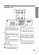


Rear
Panel
8
Caution
Do
not touch
the
inner
pins
of
the
jacks
on
the
rear
panel.
Electrostatic
discharge
may
cause
permanent
damage
to
the
unit.
Caution
When
you
select
the
function
mode
to
VIDEO1
using
the
VIDEO1
button
on
the
remote
control,
the
signal
is
output
from
the
front
L/R
speakers,
but
not
from
the
VIDEO1
VIDEO
OUT
and
AUDIO
OUT
L/R
connectors.
*
VIDEO
SELECTOR
switch
You
can
enjoy
NTSC
or
PAL
discs
by
setting
the
VIDEO
SELECTOR
switch
to
choose
the
appropriate
system.
PAL:
Select
when
DVD
receiver
is
connected
with
PAL-TV.
NTSC:
Select
when
DVD
receiver
is
connected
with
NTSC-TV.
AUTO:
Select
when
DVD
receiver
is
connected
with
Multi
system
TV.
?
When
the
selected
System
Select
switch
does
not
coincide
with
the
system
of
your
TV,
normal
color
picture
may
not
be
displayed.
?
Set
System
Select
switch
when
the
power
is
turned
off.
S-VIDEO
OUT
Connector
FM
300Ω
Antenna
Connector
AM
Antenna
Connectors
WOOFER
OUT
Connector
VIDEO
2
(Input)
Connectors
VIDEO
1
(Input/Output)
Connectors
SPEAKER
Connectors
POWER
CORD
Connect
to
an
AC
220-240V,
50/60Hz
outlet
only.
VIDEO
SELECTOR
Switch
Refer
to
explanation
below*.
COMPONENT
VIDEO
OUT
(Y
Pb
Pr)
Connectors
VIDEO
OUT
SELECTOR
Switch
Refer
to
explanation
below**.
MONITOR
OUT
Connector
OPTICAL
IN
Connector
Dust
protection
cap
Remove
the
dust
protection
cap
from
the
OPTICAL
DIGITAL
OUT
jack
and
connect
the
optical
digital
cable
(not
supplied)
securely
so
that
the
configurations
of
both
the
cable
and
the
connector
match.
Keep
the
dust
protection
cap
and
always
reattach
the
cap
when
not
using
the
connector
to
protect
against
dust
intrusion.
Dust
protection
cap
**
VIDEO
OUT
SELECTOR
Switch
Select
either
S-VIDEO
OUT
or
COMPONENT
VIDEO
OUT,
depending
on
how
you
connected
the
DVD
Receiver
to
the
TV.