User's Guide L1780U L1980U L1780Q L1980Q L1781Q L1981Q L1780Q Plus L1980Q Plus Make sure to read the Important Precautions before using the product. Keep the User's Guide(CD) in an accessible place for furture reference. See the label attached dealer when you on the product and quote this information to your require service.
Precautions Important This unit has been engineered and manufactured to ensure your personal safety, however improper use may result in potential eletrical shock or fire hazards. In order to allow the proper operation of all safeguards incorporated in this display, observe the following basic rules for its installation, use, and servicing. On Safety power cord supplied with the unit.
On Installation Do not allow anything to rest upon or roll over the power cord, and do not the display where the power cord is subject to damage. Do not use this display sink, laundry tub, in near water a wet such basement, as near a or near a place bathtub, washbowl, kitchen swimming pool. Displays are provided with ventilation openings in the cabinet to allow the release of heat generated during operation.
the Connecting Before Display setting up the monitor, that the power to the monitor, the computer system, and other attached devices is turned off. For the desktop monitor, install the computer with the stand unfolded, for the rack wall mounting, install the computer with the stand folded. Unfolding the stand ensure base 1. Place the monitor with its front facing downward on a cushion or soft cloth. 2.
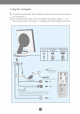
Connecting the Display Using the Computer 1. Connect the signal cable. When attached, tighten the thumbscrews to secure the connection. 2. Connect the power cable with the AC adapter (AC power supply) ②, and then plug the cable in the outlet. ③ (Voltage will be automatically controlled.
Connecting the 3. Touch Display button panel to turn the power on. monitor power is turned on, the 'Self Image Setting Function' executed automatically.(Only Analog Mode) on the front switch NOTE Self Image ' When is Setting Function'? This function provides the user with optimal display settings.When the user connects the monitor for the first time, this function automatically adjusts the display to optimal settings for individual input signals.
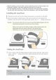
Using the Auto Pivot, Auto Mirror function This model supports Auto Pivot (automatic (automatic up/down reversal) functions. To rotation) and Auto Mirror this function, install the provided Forte Manager software first and then, perform Automatic setting.(Manual is the default setting when you purchase the - - use product.) guide included in the CD for more details on the installation method. For the automatic setting, select Forte Manager -> Option -> Pivot -> Enable AutoPivot.
Using the Auto Pivot, Auto Mirror function Auto Mirror Screen switch : The monitor screen part is automatically mirrored when you switch it forward/backward as shown in the figure. ※Caution : Be careful not to touch the the This rear rotating screen. Be careful that your hands the button section when are not pressed down when rotating screen. view represents a general model, your display may differ from the view as shown.
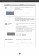
Control Panel Functions Front Panel Controls MENU (-) (+) ENGINE SOURCE AUTO/SET Control MENU Button Function Use this button to enter or exit the On Screen Display. OSD LOCKED/UNLOCKED This function allows you to lock the current control settings, so that they cannot be inadvertently changed. Touch and hold the MENU button for 5 seconds. The message "OSD LOCKED" should appear.
Control Panel Functions Control -+ - Function Buttons Use these buttons to select Screen + Button in the On Display. hot Button For adjust functions or more key information, refer to page A15 SOURCE hot key Use this button to make Dsub or DVI connector active. This feature is used when two computers are connected to the display. The default setting is Dsub. AUTO/SET Use this button to enter Button Display.
On Screen Screen Display (OSD) Control Adjustment Adjustment Making adjustments to the image size, position and operating parameters of the display is quick and easy with the On Screen Display Control system. A short example is given below to familiarize you with the use of the controls. The following section is an outline of the available adjustments and selections you can make using the OSD.
On Screen Display(OSD) Selection and Adjustment following table indicates all the On Screen Display control, adjustment, and setting menus.
On Screen Display(OSD) Selection and Adjustment procedure of selecting and adjusting an item using the OSD system. Listed below are the icons, icon names, and icon descriptions of the all items shown on the Menu. You were introduced to the Touch the MENU Button, then the main menu of the OSD appears.
On Screen Selection and Display(OSD) Main menu Sub Adjustment Description menu PICTURE PICTURE BRIGHTNESS To adjust the brightness of the CONTRAST To adjust the GAMMA Set your own gamma value. : -50/0/50 On the monitor, high gamma values display whitish images and low gamma values display high contrast images. screen. contrast of the screen. MENU : Exit : Decrease + : Increase SET : Select another sub-menu - COLOR COLOR Select the screen color. 6500K: Slightly reddish white.
On Screen Display(OSD) Main Selection and Sub menu Adjustment Description menu TRACKING TRACKING CLOCK To minimize any vertical bars or stripes visible on the screen background.The horizontal screen size will also change. PHASE To adjust the focus of the display. This item allows you to remove any horizontal noise and clear or sharpen the image of characters.
On Screen Display(OSD) The OSD screen Selection and Adjustment will appear when you touch the (-) button at the front side of the monitor. Menu Name Icons Sub-menu Name FLATRON F-ENGINE Screen when applied Screen when not applied When you execute F-ENGINE, two tones will appear on the screen as shown. The applied screen will the left side, whereas the non-applied screen will appear on the right side.Touch the SETbutton to use the adjusted screen.
Troubleshooting Check the No following before calling for service. image appears Is the power cord of the display connected? Check and Is the power indicator light on? Touch the Power button. Is the power on and the power indicator blue or Adjust the brightness and the contrast. properly if the power cord is connected to the power outlet. see green? Is the power indicator amber? display is in power saving mode, try moving the mouse or pressing any key on the keyboard to bring up the screen.
Troubleshooting Display image Display is incorrect Position is incorrect. Touch the AUTO/SET button to automatically adjust your display image to the ideal setting. If the results are unsatisfactory, adjust the image position using the H position and V position icon in the on screen display. Check Control Panel --> Display --> Settings and see if the frequency or the resolution were changed. If yes, readjust the video card to the recommend resolution.
Troubleshooting Have you installed the Have you installed the display driver? Do you see an "Unrecognized monitor, Plug&Play (VESA DDC) driver? display Be display driver from the display driver CD (or diskette) that comes with your display. Or, you can also download the driver from our web site: http://www.lge.com. sure Make to install the sure to check if the video card Plug&Play function.
17inch Specifications Display 17 inches (43.2cm) Flat Panel Active matrix-TFT LCD Anti-Glare coating 17 inches viewable 0.264mm Sync Input pixel pitch Horizontal Freq. 30 30 Vertical Video Input 56 Freq. - - - 83kHz 71kHz (Analog) (Digital) 75Hz (Automatic) Input Form Separate TTL, Positive/Negative SOG (Sync On Green) Digital Signal Input 15 pin D-Sub Connector DVI D connector - Input Form RGB Analog (0.
19inch Specifications Display 19 inches (48.18cm) Flat Panel Active matrix-TFT LCD Anti-Glare coating 19 inches viewable 0.294 Sync Input mm pixel pitch Horizontal Freq. 30 30 Vertical Video Input 56 Freq. 83kHz - 71kHz - 75Hz (Automatic) - Input Form Separate TTL, Positive/Negative SOG (Sync On Green) Digital Signal Input 15 pin D-Sub Connector DVI Resolution (Analog) (Digital) - D connector Input Form RGB Analog (0.
Specifications Preset Modes (Resolution) 17 inch monitor Display Modes (Resolution) VGA VGA VGA VESA VESA VESA MAC VESA VESA MAC VESA VESA VESA 123456789 10 11 *12 13 Horizontal Freq. (kHz) Vertical Freq. (Hz) 640 x 350 31.469 70 720 x 400 31.468 70 640 640 x 31.469 60 x 480 480 37.500 75 800 x 600 60 800 x 600 37.879 46.875 832 x 624 49.725 75 75 1024 x 768 48.363 60 1024 1152 x 60.023 75 x 768 870 68.681 75 1152 x 900 65 1280 x 1024 61.805 63.
How to Install the Rack wall This monitor meets mounting VESA-compliant mounting interface pad specifications. Accessories 1 Installation 2 Rack guide 4 Screws for wall mount rack This rear view represents a - 4EA 3 Anchor - 4EA 5 Screws for monitor stationary rack-4EA general model; your display may differ from the view as shown. 1 ■Mark the locations of the 2 racks that are to be mounted and drill fourholes 40 mm or deeper in the wall.
How to Install the Rack wall mounting 3 ■Put the monitor on a soft cloth or cushion with its front facing downward. stand, push the folding stopper inwards until you hear the“click” sound using a coin or“- shape screw driver, while pressing down the stand base to ■To fix a “ the monitor.
Digitally yours