
Engineering Manual
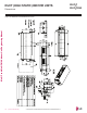
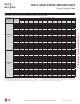
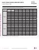
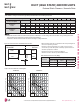
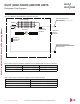
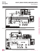
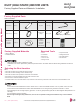
Table Of Contents
- Convergence of Technology, Innovation, Flexibility, & Style
- Unit Nomenclature
- Outdoor Unit Overview
- Indoor Unit Overview
- Controls and Options Overview
- Art Cool Mirror Indoor Units
- General Data / Specifications
- Dimensions
- Cooling Capacity Table
- Heating Capacity Table
- Acoustic Data
- Air Velocity and Temperature Distribution
- Refrigerant Flow Diagram
- Wiring Diagram
- Factory Supplied Parts and Materials
- Installation and Best Layout Practices
- Art Cool Gallery Indoor Units
- General Data / Specifications
- Dimensions
- Cooling Capacity Table
- Heating Capacity Table
- Acoustic Data
- Air Velocity and Temperature Distribution
- Refrigerant Flow Diagram
- Wiring Diagram
- Factory Supplied Parts and Materials
- Installation and Best Layout Practices
- Standard Wall-Mounted Indoor Units
- General Data / Specifications
- Dimensions
- Cooling Capacity Table
- Heating Capacity Table
- Acoustic Data
- Air Velocity and Temperature Distribution
- Refrigerant Flow Diagram
- Wiring Diagram
- Factory Supplied Parts and Materials
- Installation and Best Layout Practices
- Duct (Low Static) Indoor Units
- General Data / Specifications
- Dimensions
- Cooling Capacity Table
- Heating Capacity Table
- External Static Pressure
- Acoustic Data
- Refrigerant Flow Diagrams
- Wiring Diagram
- Factory Supplied Parts and Materials
- Installation and Best Layout Practices
- Duct (High Static) Indoor Units
- General Data / Specifications
- Dimensions
- Cooling Capacity Table
- Heating Capacity Table
- External Static Pressure / Acoustic Data
- Refrigerant Flow Diagrams
- Wiring Diagrams
- Factory Supplied Parts and Materials / Installation
- Installation and Best Layout Practices
- Four-Way Ceiling Cassette Indoor Units
- General Data / Specifications
- Dimensions
- Dimensions
- Cooling Capacity Table
- Heating Capacity Table
- Acoustic Data
- Air Velocity and Temperature Distribution
- Refrigerant Flow Diagram
- Wiring Diagram
- Factory Supplied Parts and Materials
- Installation and Best Layout Practices
- Vertical-Horizontal Indoor Units
- General Data / Specifications
- Dimensions
- Cooling Capacity Table
- Heating Capacity Table
- External Static Pressure
- Acoustic Data
- Refrigerant Flow Diagram
- Wiring Diagram
- Factory Supplied Parts and Materials
- Installation and Best Layout Practices
- Equipment Selection Procedure
- Building Ventilation Design Guide
- Placement Considerations
- Refrigerant Piping Design
- Design Guideline Summary
- Creating a Balanced System / Manual Layout Procedure
- LG Engineered Multi F MAX Y-Branch Kit
- Refrigerant Charge
- Installation & Layout Best Practices
- Refrigerant Piping System Layout
- Piping Insulation
- Condensate Drain Piping
- Y-Branch Kit
- Wiring Connections
- Power Wiring (208-230V) and Communications Cable Details
- Indoor Unit Group Control
- Acronyms

MULTI
F
MAX
MULTI
F
Refrigerant Flow Diagrams
Figure 159: LMHN240HV and LMHN360HV Refrigerant Flow Diagram.
Table 60: Multi F Ceiling-Concealed Duct (High Static) Indoor Unit Refrigerant Pipe Connection Port Diameters.
Model No. Vapor (inch) Liquid (inch)
LMHN240HV Ø1/2 Ø1/4
LMHN360HV Ø5/8 Ø3/8
Table 61: Multi F Ceiling-Concealed Duct (High Static) Indoor Unit Thermistor Details.
Description (Based on Cooling Mode) PCB Connector
Indoor Air Temperature Thermistor CN-ROOM
Evaporator Inlet Temperature Thermistor CN-PIPE/IN
Evaporator Outlet Temperature Thermistor CN-PIPE/OUT
Sirocco Fan
Heat exchanger
Gas pipe connection port
(flare connection)
Liquid pipe connection port
(flare connection)
Cooling
Heating
M
Thermistor for
suction air
temperature
Thermistor for
evaporator outlet
temperature
Thermistor for
evaporator inlet
temperature
DUCT (HIGH STATIC) INDOOR UNITS
Due to our policy of continuous product innovation, some specications may change without notication.
©LG Electronics U.S.A., Inc., Englewood Cliffs, NJ. All rights reserved. “LG” is a registered trademark of LG Corp.
118 | DUCT (HIGH STATIC)
Multi F and Multi F MAX Indoor Unit Engineering Manual