
Engineering Manual
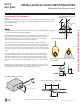
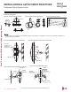
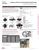
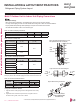
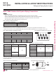
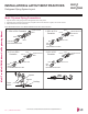
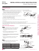
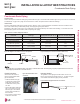
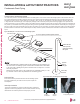
Table Of Contents
- Convergence of Technology, Innovation, Flexibility, & Style
- Unit Nomenclature
- Outdoor Unit Overview
- Indoor Unit Overview
- Controls and Options Overview
- Art Cool Mirror Indoor Units
- General Data / Specifications
- Dimensions
- Cooling Capacity Table
- Heating Capacity Table
- Acoustic Data
- Air Velocity and Temperature Distribution
- Refrigerant Flow Diagram
- Wiring Diagram
- Factory Supplied Parts and Materials
- Installation and Best Layout Practices
- Art Cool Gallery Indoor Units
- General Data / Specifications
- Dimensions
- Cooling Capacity Table
- Heating Capacity Table
- Acoustic Data
- Air Velocity and Temperature Distribution
- Refrigerant Flow Diagram
- Wiring Diagram
- Factory Supplied Parts and Materials
- Installation and Best Layout Practices
- Standard Wall-Mounted Indoor Units
- General Data / Specifications
- Dimensions
- Cooling Capacity Table
- Heating Capacity Table
- Acoustic Data
- Air Velocity and Temperature Distribution
- Refrigerant Flow Diagram
- Wiring Diagram
- Factory Supplied Parts and Materials
- Installation and Best Layout Practices
- Duct (Low Static) Indoor Units
- General Data / Specifications
- Dimensions
- Cooling Capacity Table
- Heating Capacity Table
- External Static Pressure
- Acoustic Data
- Refrigerant Flow Diagrams
- Wiring Diagram
- Factory Supplied Parts and Materials
- Installation and Best Layout Practices
- Duct (High Static) Indoor Units
- General Data / Specifications
- Dimensions
- Cooling Capacity Table
- Heating Capacity Table
- External Static Pressure / Acoustic Data
- Refrigerant Flow Diagrams
- Wiring Diagrams
- Factory Supplied Parts and Materials / Installation
- Installation and Best Layout Practices
- Four-Way Ceiling Cassette Indoor Units
- General Data / Specifications
- Dimensions
- Dimensions
- Cooling Capacity Table
- Heating Capacity Table
- Acoustic Data
- Air Velocity and Temperature Distribution
- Refrigerant Flow Diagram
- Wiring Diagram
- Factory Supplied Parts and Materials
- Installation and Best Layout Practices
- Vertical-Horizontal Indoor Units
- General Data / Specifications
- Dimensions
- Cooling Capacity Table
- Heating Capacity Table
- External Static Pressure
- Acoustic Data
- Refrigerant Flow Diagram
- Wiring Diagram
- Factory Supplied Parts and Materials
- Installation and Best Layout Practices
- Equipment Selection Procedure
- Building Ventilation Design Guide
- Placement Considerations
- Refrigerant Piping Design
- Design Guideline Summary
- Creating a Balanced System / Manual Layout Procedure
- LG Engineered Multi F MAX Y-Branch Kit
- Refrigerant Charge
- Installation & Layout Best Practices
- Refrigerant Piping System Layout
- Piping Insulation
- Condensate Drain Piping
- Y-Branch Kit
- Wiring Connections
- Power Wiring (208-230V) and Communications Cable Details
- Indoor Unit Group Control
- Acronyms

INSTALLATION & LAYOUT BEST PRACTICES
Refrigerant Piping System Layout
Multi F MAX Outdoor Unit System Piping Connections
Branch Distribution to Indoor Unit Piping Connections
• Install indoor unit liquid and vapor refrigerant pipes (and connection wiring) to the appropriate branch distribution ports.
• Clearly note on the indoor unit’s refrigerant piping (liquid, vapor) which branch distribution port it is connected to (A, B, C, D).
Outdoor Unit Piping Connections LMU540HV
Liquid Line Connection (in., OD) x Qty. 3/8 x 1
Vapor Line Connection (in., OD) x Qty. 3/4 x 1
Avoid Pipe Damage
• When routing field-provided piping, avoid damaging the outdoor unit from excessive vibration.
• Correctly route the piping so it does not make contact with mounting bolts. Allow room for field installation.
• Properly insulate the liquid and gas lines separately up to the point of connection at the unit frame.
• See table below for Multi F MAX outdoor unit connection types.
Table 123:Outdoor Unit Piping Connections.
Table 124:Branch Distribution Unit Piping Connections.
Table 125:Indoor Unit Pipe Sizes.
Branch Distribution Unit PMBD3620 PMBD3630 PMBD3640 PMBD3641
Piping Connections to Outdoor Unit
Liquid (in., OD) x Qty. Ø3/8 x 1
Vapor (in., OD) x Qty. Ø3/4 x 1
Piping Connections to Indoor Units
Liquid (in., OD) x Qty. Ø1/4 x 2 Ø1/4 x 3 Ø1/4 x 4 Ø1/4 x 3, Ø3/8 x 1
Vapor (in., OD) x Qty. Ø3/8 x 2 Ø3/8 x 3 Ø3/8 x 4 Ø3/8 x 3, Ø5/8 x 1
Table 126:Connection Socket Dimensions.
Connection sockets (included as a factory-supplied accessory with the indoor units) may need to be used when piping the indoor units to the
branch distribution unit.
Connection Socket
A
B
Figure 284:Branch Distribution Ports to Indoor Units.
ABC D
Figure 285:Connection Socket Diagram.
Indoor Unit Capacity
Vapor Line
Connection (in., OD)
Liquid Line
Connection (in., OD)
7,000 Btu/h
Ø3/8
Ø1/4
9,000 Btu/h
12,000 Btu/h
15,000 Btu/h
18,000 Btu/h
Ø1/2
24,000 Btu/h
36,000 Btu/h Ø5/8 Ø3/8
Table 127:Indoor Unit Piping Connections.
Indoor Unit Capacity
Vapor Line
Connection (in., OD)
Liquid Line
Connection (in., OD)
7,000 Btu/h
Ø3/8 Ø1/4
9,000 Btu/h
12,000 Btu/h
15,000 Btu/h
18,000 Btu/h Ø5/8 Ø3/8
24,000 Btu/h Ø1/2 Ø1/4
36,000 Btu/h Ø5/8 Ø3/8
Indoor Unit Capacity
Vapor (in., OD) Liquid (in., OD)
A B A B
18,000 Btu/h Ø3/8 → Ø1/2, Ø1/2 → Ø5/8 Ø1/4 → Ø3/8
24,000 Btu/h Ø3/8 → Ø1/2 N/A
36,000 Btu/h Ø1/2 → Ø5/8 Ø1/4 → Ø3/8
Due to our policy of continuous product innovation, some specications may change without notication.
©LG Electronics U.S.A., Inc., Englewood Cliffs, NJ. All rights reserved. “LG” is a registered trademark of LG Corp.
DESIGN & PRACTICES | 205
Refrigerant Piping Design and Best Practices
MULTI
F
MAX
MULTI
F