
Engineering Manual

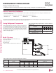
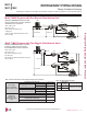
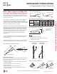
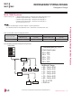
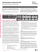
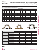
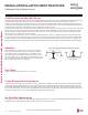
Table Of Contents
- Convergence of Technology, Innovation, Flexibility, & Style
- Unit Nomenclature
- Outdoor Unit Overview
- Indoor Unit Overview
- Controls and Options Overview
- Art Cool Mirror Indoor Units
- General Data / Specifications
- Dimensions
- Cooling Capacity Table
- Heating Capacity Table
- Acoustic Data
- Air Velocity and Temperature Distribution
- Refrigerant Flow Diagram
- Wiring Diagram
- Factory Supplied Parts and Materials
- Installation and Best Layout Practices
- Art Cool Gallery Indoor Units
- General Data / Specifications
- Dimensions
- Cooling Capacity Table
- Heating Capacity Table
- Acoustic Data
- Air Velocity and Temperature Distribution
- Refrigerant Flow Diagram
- Wiring Diagram
- Factory Supplied Parts and Materials
- Installation and Best Layout Practices
- Standard Wall-Mounted Indoor Units
- General Data / Specifications
- Dimensions
- Cooling Capacity Table
- Heating Capacity Table
- Acoustic Data
- Air Velocity and Temperature Distribution
- Refrigerant Flow Diagram
- Wiring Diagram
- Factory Supplied Parts and Materials
- Installation and Best Layout Practices
- Duct (Low Static) Indoor Units
- General Data / Specifications
- Dimensions
- Cooling Capacity Table
- Heating Capacity Table
- External Static Pressure
- Acoustic Data
- Refrigerant Flow Diagrams
- Wiring Diagram
- Factory Supplied Parts and Materials
- Installation and Best Layout Practices
- Duct (High Static) Indoor Units
- General Data / Specifications
- Dimensions
- Cooling Capacity Table
- Heating Capacity Table
- External Static Pressure / Acoustic Data
- Refrigerant Flow Diagrams
- Wiring Diagrams
- Factory Supplied Parts and Materials / Installation
- Installation and Best Layout Practices
- Four-Way Ceiling Cassette Indoor Units
- General Data / Specifications
- Dimensions
- Dimensions
- Cooling Capacity Table
- Heating Capacity Table
- Acoustic Data
- Air Velocity and Temperature Distribution
- Refrigerant Flow Diagram
- Wiring Diagram
- Factory Supplied Parts and Materials
- Installation and Best Layout Practices
- Vertical-Horizontal Indoor Units
- General Data / Specifications
- Dimensions
- Cooling Capacity Table
- Heating Capacity Table
- External Static Pressure
- Acoustic Data
- Refrigerant Flow Diagram
- Wiring Diagram
- Factory Supplied Parts and Materials
- Installation and Best Layout Practices
- Equipment Selection Procedure
- Building Ventilation Design Guide
- Placement Considerations
- Refrigerant Piping Design
- Design Guideline Summary
- Creating a Balanced System / Manual Layout Procedure
- LG Engineered Multi F MAX Y-Branch Kit
- Refrigerant Charge
- Installation & Layout Best Practices
- Refrigerant Piping System Layout
- Piping Insulation
- Condensate Drain Piping
- Y-Branch Kit
- Wiring Connections
- Power Wiring (208-230V) and Communications Cable Details
- Indoor Unit Group Control
- Acronyms

Type ACR copper is the only approved refrigerant pipe material for
use with LG Multi F air conditioning products. ACR rated tubing is the
only type that ships with yellow caps. Approved tubing for use with
Multi V products will be marked “R410 RATED” along the length of
the tube.
• Drawn temper (rigid) ACR copper tubing is available in sizes 3/8
through 2-1/8 inches (ASTM B 280, clean, dry, and capped).
• Annealed temper (soft) ACR copper tubing is available in sizes 1/4
through 2-1/8 inches (ASTM B 280, clean, dry, and capped).
Tube wall thickness should meet local code requirements and be
approved for a maximum operating pressure of 551 psi. When bend-
ing tubing, use the largest radii possible to reduce the equivalent
length of installed pipe; also, bending radii greater than ten (10) pipe
diameters can minimize pressure drop. Be sure no traps or sags are
present when rolling out soft copper tubing coils.
OD (in)
1/4 3/8 1/2 5/8 3/4
Material
Rigid or Soft ACR Acceptable
Rigid or Solid ACR Rated
for R410A
Min. Bend
Radius (in)
.563 .9375 1.5 2.25 3.0
Min. Wall
Thickness (in)
.031 .031 .031 .039 .039
Table 114: ACR Rated Copper Tubing Material.
Type
Seamless Phosphorous Deoxidized
Class
UNS C12200 DHP
Straight Lengths
H58 Temper
Coils
O60 Temper
Table 115: ACR Rated Piping Tube Thicknesses.
Under normal operating conditions, the vapor pipe temperature of a
Multi F system can vary as much as 180°F. With this large
variance in pipe temperature, the designer must consider pipe
expansion and contraction to avoid pipe and fitting fatigue failures.
Refrigerant pipe, along with the insulation jacket, form a cohesive
unit that expands and contracts together. During system operation,
thermal heat transfer occurs between the pipe and the surrounding
insulation.
If the pipe is mounted in free air space, no natural restriction to
movement is present if mounting clamps are properly spaced and
installed. When the refrigerant pipe is mounted underground in a
utility duct stacked among other pipes, natural restriction to linear
movement is present. In extreme cases, the restrictive force of
surface friction between insulating jackets could become so great
that natural expansion ceases and the pipe is “fixed” in place. In this
situation, opposing force caused by change in refrigerant fluid/vapor
temperature can lead to pipe/fitting stress failure.
The refrigerant pipe support system must be engineered to allow
free expansion to occur. When a segment of pipe is mounted
between two fixed points, provisions must be provided to allow pipe
expansion to naturally occur. The most common method is the
inclusion of expansion Loop or U-bends mounted in the horizontal
plane. When expansion loops are placed in a vertical riser, the loop
is to be formed in a horizontal fashion resulting in a torsional move-
ment during expansion and contraction. Each segment of pipe has
a natural fixed point where no movement occurs. This fixed point is
located at the center point of the segment assuming the entire pipe
is insulated in a similar fashion. The natural fixed point of the pipe
segment is typically where the expansion Loop or U-bend should be.
Linear pipe expansion can be calculated using the following formula:
1. From Table 115, find the row corresponding with the actual length
of the straight pipe segment.
2. Estimate the minimum and maximum temperature of the pipe.
Typical pipe temperature change range: High Pressure Vapor:
ambient temperature to 215°F; Low Pressure Vapor: ambient to
35°F; Liquid pipe: ambient, 80°F, 110°F. Choose the two most
extreme. In the column showing the minimum pipe temperature,
look up the anticipated expansion distance. Do the same for the
maximum pipe temperature.
3. Calculate the difference in the two expansion distance values.
The result will be the anticipated change in pipe length.
Example:
A Multi F MAX system is installed and the design shows that there
is a 100 foot straight segment of tubing between a Y-branch and
a branch distribution unit. The system operates 24 hours per day.
In heating, this pipe transports hot gas vapor to the indoor units at
120°F. In cooling, the same tube is a suction line returning refriger-
ant vapor to the outdoor unit at 40°F. Look up the copper tubing
expansion at each temperature and calculate the difference.
Vapor Line
Transporting Hot Vapor: 100 ft. pipe at 120°F = 1.40 in.
Transporting Suction Vapor: 100 ft. pipe at 40°F = 0.40 in.
Anticipated Change in Length: 1.40 in. – 0.40 in. = 1.00 in.
Liquid Line
The liquid temperature remains the same temperature; only the
direction of flow will reverse. Therefore, no significant change in
length of the liquid line is anticipated.
When creating an expansion joint, the joint depth should be a
minimum of two times the joint width. Although different types of
expansion arrangements are available, the data for correctly sizing
an expansion loop is provided in Table 117. Use soft copper with
long radius bends on longer runs or long radius elbows for shorter
pipe segments. Using the anticipated linear expansion (LE) distance
calculated, look up the Expansion Loop or U-bend minimum design
dimensions. If other types of expansion joints are chosen, design
per ASTM B-88 Standards.
LE = C x L x (T
r
– T
a
) x 12
LE = Anticipated linear tubing expansion (in.)
C = Constant (For copper = 9.2 x 10
-6
in./in.°F)
L = Length of pipe (ft.)
T
R
= Refrigerant pipe temperature (°F)
T
a
= Ambient air temperature (°F)
12 = Inches to feet conversion (12 in./ft.)
Selecting Field-Supplied Copper Tubing
Copper Expansion and Contraction
REFRIGERANT PIPING DESIGN
Due to our policy of continuous product innovation, some specications may change without notication.
©LG Electronics U.S.A., Inc., Englewood Cliffs, NJ. All rights reserved. “LG” is a registered trademark of LG Corp.
198 | DESIGN & PRACTICES
Multi F and Multi F MAX Indoor Unit Engineering Manual
MULTI
F
MAX
MULTI
F