MULTI F MULTI F MAX HEAT PUMP SYSTEM ENGINEERING MANUAL Multi-Zone Heat Pump Systems 1.
PROPRIETARY DATA NOTICE This document, as well as all reports, illustrations, data, information, and other materials are the property of LG Electronics U.S.A., Inc., and are disclosed by LG Electronics U.S.A., Inc. only in confidence. This document is for design purposes only. A summary list of safety precautions is on page 3.
TABLE OF CONTENTS Unit Nomenclature.......................................................................................................................................................................................................... 4 LG Air Conditioner Technical Solution (LATS) ......................................................................................................................................................... 5-6 Manual Equipment Selection Procedure.................................
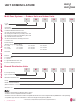
MULTI F MULTI F MAX UNIT NOMENCLATURE Multi-Zone Systems — Outdoor Units and Indoor Units Multi F and Multi F MAX Heat Pump System Engineering Manual L M U 30 3 HV 36 2 0 L = LG Type: M = Multi-Zone Component: AN: Art Cool™ Wall-Mounted Indoor Unit N: Standard Wall-Mounted Indoor Unit CN: Four-Way Ceiling-Cassette Indoor Unit DN: Ceiling-Concealed Duct (Low Static) Indoor Unit HN: Ceiling-Concealed Duct (High Static) Indoor Unit QN: Low-Wall Console Indoor Unit VN: Vertical-Horizontal Air Handl
MULTI F MULTI F MAX LG AIR CONDITIONER TECHNICAL SOLUTION (LATS) LG Air Conditioner Technical Solution (LATS) Software A properly designed and installed refrigerant piping system is critical to the optimal performance of LG air-conditioning systems. To assist engineers, LG offers, free of charge, LG Air Conditioner Technical Solution (LATS) software—a total design solution for LG air conditioning systems.
LG AIR CONDITIONER TECHNICAL SOLUTION (LATS) MULTI F MULTI F MAX LATS Generates a Complete Project Report Multi F and Multi F MAX Heat Pump System Engineering Manual LATS software also generates a report containing project design parameters, cooling and heating design data, system component performance, and capacity data.
MULTI F MULTI F MAX MANUAL EQUIPMENT SELECTION PROCEDURE To use the manual equipment selection procedure in choosing the multi-zone system that is the most appropriate for the space, as with traditional air-conditioning systems, follow similar protocols outlined in Manual J from the Air Conditioning Contractors of America (ACCA; see www.acca.org). 1. Obtain the design conditions, and calculate the maximum cool and heat loads for the structure. 2.
MULTI F MULTI F MAX MANUAL EQUIPMENT SELECTION PROCEDURE Examples Multi F and Multi F MAX Heat Pump System Engineering Manual Example 1 Branch Distribution Unit (PMBD3641) Outdoor Unit: LMU541HV First Indoor Unit: + Second Indoor Unit: + Third Indoor Unit: LMCN128HV LSN090HSV5 LMVN361HV Total Capacity Index = 12 + 9 + 36 x 1.
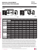
MULTI F MULTI F MAX MANUAL EQUIPMENT SELECTION PROCEDURE Table 2: Rated Outdoor Unit Capacity. Rated Capacity (Btu/h)* Cooling Heating Min. No. of IDUs Connectable Max. No. of IDUs Indoor Min. Capacity Index Units Max.
MULTI F MULTI F MAX MANUAL EQUIPMENT SELECTION PROCEDURE Multi F and Multi F MAX Heat Pump System Engineering Manual Using the System Combination Tables Multi F system combination tables illustrate how each indoor unit receives a percentage of total outdoor unit rated capacity.
MULTI F MULTI F MAX MANUAL EQUIPMENT SELECTION PROCEDURE Table 4: Multi F MAX Outdoor Unit to Branch Distribution Unit Refrigerant Line Length Derates. Main Piping Length (feet) 16.4 32.8 49.2 65.6 82.0 98.4 114.8 131.2 147.6 164.0 180.4 Cooling Capacity (%) 100.0 98.8 97.3 95.8 94.3 92.8 91.3 89.8 88.3 86.8 85.3 Heating Capacity (%) 100.0 99.6 99.2 98.7 98.3 97.8 97.4 96.9 96.5 96.0 95.
MULTI F MULTI F MAX MANUAL EQUIPMENT SELECTION PROCEDURE Altitude Correction Factor The impact of air density must be considered on systems installed at a significant altitude above sea level, therefore, locally accepted altitude correction factors must be applied. Multi F and Multi F MAX Heat Pump System Engineering Manual Defrost Correction Factor for Heating Operation The outdoor unit heating capacity may need to be adjusted for frost accumulation on air-cooled systems.
MULTI F OUTDOOR UNIT DATA Mechanical Specifications on page 14 General Data on page 15 Electrical Data on page 17 Functions, Controls, Options, and Accessories on page 18 Dimensions on page 19 Center of Gravity / Corner Weights on page 21 Wiring Diagrams on page 22 Refrigerant Flow Diagrams on page 24 Acoustic Data on page 27 Operation Ranges on page 29
MULTI F MULTI F MAX MULTI F OUTDOOR UNIT 0HFKDQLFDO 6SHFL¿FDWLRQV Multi F Heat Pump Condensing Units Multi F and Multi F MAX Heat Pump System Engineering Manual General Figure 4: Multi F LMU183HV and LMU243HV Outdoor Units. Figure 5: Multi F LMU303HV and LMU363HV Outdoor Units.
MULTI F MULTI F MAX MULTI F OUTDOOR UNIT General Data 1 Capacity is rated with non-ducted indoor units, 0 ft. above sea level, with a 0 ft. level difference between outdoor and indoor units, and the following refrigerant pipe lengths: LMU183HV: 16.4 ft. x 2 = 32.8 ft. LMU243HV: 16.4 ft. x 3 = 49.2 ft. LMU303HV: 16.4 ft. x 4 = 65.6 ft. LMU363HV: 16.4 ft. x 4 = 65.6 ft. All capacities are net with a combination ratio between 95 – 105%.
MULTI F MULTI F MAX MULTI F OUTDOOR UNIT General Data Table 8: /08 +9 (I¿FLHQF\ 5DWLQJV 1,2 Rated Cooling System Combined With Capacity (Btu/h) Multi F and Multi F MAX Heat Pump System Engineering Manual LMU183HV Non-Ducted Indoor Units Ducted Indoor Units Mixed Non-Ducted and Ducted Indoor Units LMU243HV LMU303HV LMU363HV HSPF2 Low Heating Capacity (Btu/h) COP (17°F) 22.5 22,000 3.60 9.6 13,800 2.70 17,200 12.5 18.5 20,000 3.41 9.0 13,400 2.58 17,600 13.0 20.5 21,000 3.
MULTI F MULTI F MAX MULTI F OUTDOOR UNIT Electrical Data Electrical Data Table 12: Electrical Data. Nominal Tons Unit Model No. 1.5 2 2.5 3 LMU183HV LMU243HV LMU303HV LMU363HV Voltage Compressor Hertz Voltage Range MCA MOP LRA Compressor Quantity Motor RLA (Min. to Max.) 60 Voltage tolerance is ±10%. Maximum allowable voltage unbalance is 2%. RLA = Rated Load Amps. MCA = Minimum Circuit Ampacity. LRA = (Locked Rotor Amps) 208 - 230 187 - 253 15.8 16.0 18.4 18.4 20 20 25 25 16.0 16.0 19.0 19.
MULTI F MULTI F MAX MULTI F OUTDOOR UNIT )XQFWLRQV &RQWUROV 2SWLRQV DQG $FFHVVRULHV Reliability Building Central Convenience Network Integration Solution Controllers Unit Defrost / Deicing High Pressure Switch Low Pressure Switch Phase Protection Restart Delay (Three [3] Minutes) Self Diagnosis Soft Start Test Function Night Silent Operation Wiring Error Check Peak Control Mode Lock Forced Cooling Operation (Outdoor Unit) LMU183HV ¥ X X X ¥ ¥ ¥ ¥ ¥ ¥ ¥ ¥ ¥ LMU243HV ¥ X X X ¥ ¥ ¥ ¥ ¥ ¥ ¥ ¥ ¥ LMU303H
MULTI F MULTI F MAX MULTI F OUTDOOR UNIT 'LPHQVLRQV Figure 6: LMU183HV and LMU243HV External Dimensions. Unit: Inch Gravity point Multi F Outdoor Unit Data Notes: 1. Unit must be installed in compliance with the installation manual. 2. Unit must be grounded in accordance with the local or state regulations and applicable national codes. 3. All field-supplied electrical components and materials must comply with the local, state, and national codes. 4.
MULTI F OUTDOOR UNIT 'LPHQVLRQV MULTI F MULTI F MAX Figure 7: LMU303HV and LMU363CHV External Dimensions. [Unit : mm(inch)] Multi F and Multi F MAX Heat Pump System Engineering Manual Gravity point No. 20 | Part Name 1 Air discharge grille 2 Vapor pipe connection 3 Liquid pipe connection 4 Main service valve (Liquid) 5 Main service valve (Vapor) MULTI F OUTDOOR UNIT Notes: 1. Unit must be installed in compliance with the installation manual. 2.
MULTI F MULTI F MAX MULTI F OUTDOOR UNIT &HQWHU RI *UDYLW\ &RUQHU :HLJKWV Figure 8: LMU183HV, LMU243HV, LMU303HV, and LMU363HV Center of Gravity and Corner Weight Diagram (LMU303HV and LMU363HV appearance will differ than what is depicted below).. Multi F Outdoor Unit Data Table 14: LMU183HV, LMU243HV, LMU303HV, and LMU363HV Center of Gravity and Corner Weights. Model No. LMU183HV LMU243HV LMU303HV LMU363HV Weight (lb.) Shipping Net 109.8 110.2 154.3 154.3 Center of Gravity (in.) a b c 101.0 101.
MULTI F MULTI F MAX MULTI F OUTDOOR UNIT :LULQJ 'LDJUDPV Figure 9: LMU183HV and LMU243HV Wiring Diagram. USE COPPER SUPPLY WIRES. Multi F and Multi F MAX Heat Pump System Engineering Manual INFORMATION • You need to buy a dedicated circuit separately Factory Wiring Field Wiring Optional or Factory installed* CN_FAN_DC CN_H_PRESS CN_CP_LCN_CP_N CN_LGMV CN_AIR 250 V / T3.15 A CN_POWER 250 V / T25 A 250 V / T3.
MULTI F MULTI F MAX MULTI F OUTDOOR UNIT :LULQJ 'LDJUDPV Figure 10: LMU303HV and LMU363HV Wiring Diagram. USE COPPER SUPPLY WIRES. UTILISER DES FILS D’ALIMANTATION EN CUIVRE. INFORMATION • You need to buy a dedicated circuit separately Factory Wiring Field Wiring Optional or Factory installed* Multi F Outdoor Unit Data *This function can be optional or factory installed depending on the application model. *You must purchase the optional parts in order to use them. CN_CP_L CN_CP_N MEZ68866104 Rev.
MULTI F MULTI F MAX MULTI F OUTDOOR UNIT 5HIULJHUDQW )ORZ 'LDJUDPV Figure 11: LMU183HV Refrigerant Flow Diagram.
MULTI F MULTI F MAX MULTI F OUTDOOR UNIT 5HIULJHUDQW )ORZ 'LDJUDPV Figure 12: LMU243HV Refrigerant Flow Diagram.
MULTI F MULTI F MAX MULTI F OUTDOOR UNIT 5HIULJHUDQW )ORZ 'LDJUDPV Figure 13: LMU303HV and LMU363HV Refrigerant Flow Diagram.
MULTI F MULTI F MAX MULTI F OUTDOOR UNIT $FRXVWLF 'DWD Sound Pressure Levels • 0HDVXUHPHQW WDNHQ ƍ DERYH ILQLVKHG IORRU DQG DW D GLVWDQFH RI ƍ IURP IDFH RI XQLW • Measurements taken with no attenuation and units operating at full load normal operating condition. • Sound level will vary depending on a range of factors such as construction (acoustic absorption coefficient) of particular area in which the equipment is installed.
MULTI F MULTI F MAX MULTI F OUTDOOR UNIT $FRXVWLF 'DWD Table 19: Sound Power Levels (dB[A]). • Data is valid under diffuse field conditions. • Data is valid under nominal operating conditions. • Sound power level is measured using rated conditions, and tested in a reverberation room per ISO 3741 standards. • Sound level will vary depending on a range of factors such as construction (acoustic absorption coefficient) of particular area in which the equipment is installed. • 5HIHUHQFH DFRXVWLF LQWHQVLW\ G
MULTI F MULTI F MAX MULTI F OUTDOOR UNIT 2SHUDWLRQ 5DQJHV Figure 17: Cooling and Heating Operation Ranges. Cooling 122 118 113 95 86 Heating 77 77 59 50 41 32 23 14 50 41 32 23 Continuous Operation 14 5 0 -4 5 -4 41 68 64 59 Warming up Operation Outdoor Temperature (°F WB) Continuous Operation 68 Multi F Outdoor Unit Data Outdoor Temperature (°F DB) 104 50 57 59 68 Indoor Temperature (°F WB) 77 82.4 -13 50 59 68 77 81 86 91.
MULTI F MAX OUTDOOR UNIT DATA Mechanical Specifications on page 31 General Data on page 32 Electrical Data on page 33 Functions, Controls, Options, and Accessories on page 34 Dimensions on page 35 Center of Gravity / Corner Weight on page 37 Wiring Diagrams on page 39 Refrigerant Flow Diagrams on page 41 Acoustic Data on page 43 Operation Ranges on page 45
MULTI F MULTI F MAX MULTI F MAX OUTDOOR UNIT 0HFKDQLFDO 6SHFL¿FDWLRQV Multi F MAX Heat Pump Condensing Units General Temperature Ranges The heat pump outdoor units are capable of operating in cooling mode from 14°F to 118°F ambient dry bulb (installing an optional Low Ambient Wind Baffle Kit will allow operation down to -4°F in cooling mode for Multi F MAX systems).
MULTI F MAX OUTDOOR UNIT Multi F and Multi F MAX Heat Pump System Engineering Manual General Data MULTI F MULTI F MAX Table 20: Multi F MAX Outdoor Unit General Data. LMU481HV LMU541HV LMU601HV Model Number Capacity 10,800~48,000~58,000 10,800~50,500~63,200 10,800~60,000~65,000 Cooling (Btu/h) (Minimum ~ Rated ~ Maximum)1 0.66~3.75~5.20 0.66~4.01~5.71 0.64~5.31~5.81 Cooling Power Input (kW) (Min.~Rated~ Max.) 3.0~17.0~23.6 3.0~18.2~25.9 2.9~24.0~26.3 Cooling Running Current (A) (Min.~Rated~ Max.
MULTI F MULTI F MAX MULTI F MAX OUTDOOR UNIT General Data / Electrical Data Table 21: /08 +9 (I¿FLHQF\ 5DWLQJV 1,2 System Combined With LMU481HV Non-Ducted Indoor Units Ducted Indoor Units Mixed Non-Ducted and Ducted Indoor Units Rated Cooling EER Rated Heating COP Capacity (Btu/h) (95°F) SEER Capacity (Btu/h) (47°F) HSPF Low Heating Capacity (Btu/h) COP (17°F) 48,000 12.8 20.8 54,000 4.87 10.5 33,800 2.50 48,000 12.6 19.0 54,000 4.51 10.5 33,800 2.45 48,000 12.7 19.
MULTI F MULTI F MAX MULTI F MAX OUTDOOR UNIT )XQFWLRQV &RQWUROV 2SWLRQV DQG $FFHVVRULHV Reliability Building Central Convenience Network Integration Solution Controllers Unit Defrost / Deicing High Pressure Switch Low Pressure Switch Phase Protection Restart Delay (Three [3] Minutes) Self Diagnosis Soft Start Test Function Night Silent Operation Wiring Error Check Peak Control Mode Lock Forced Cooling Operation (Outdoor Unit) LMU481HV ¥ X X X ¥ ¥ ¥ ¥ ¥ ¥ ¥ ¥ ¥ LMU541HV ¥ X X X ¥ ¥ ¥ ¥ ¥ ¥ ¥ ¥ ¥ LMU
MULTI F MULTI F MAX MULTI F MAX OUTDOOR UNIT 'LPHQVLRQV Figure 19: LMU481HV and LMU541HV External Dimensions. Chassis code : U60A Liquid Pipe Connection (Flare) Vapor Pipe Connection (Flare) Multi F MAX Outdoor Unit Data Handle Power Wiring / Communication Cable Access Holes Air Outlet Pipe Routing Hole (Front) Pipe Routing Hole (Side) Pipe Routing Hole (Back) Notes: 1. Unit must be installed in compliance with the installation manual. 2.
MULTI F MULTI F MAX MULTI F MAX OUTDOOR UNIT 'LPHQVLRQV Figure 20: LMU601HV External Dimensions. Chassis code : U60A-B 13 24ïñ» 14ñ»๛ Multi F and Multi F MAX Heat Pump System Engineering Manual 15ïï» 6ï» (1»๛) 37ïñ» 3ïເ» 3ïñ»๛ ñï» Handle ï»๛ 24ïñ»๛ (3») Air Outlet 16ñ» 10ເ» 11ï» 4ñ» 1»๛ 9ðເ» | 5ñï» Liquid Pipe Connection (Flare) Vapor Pipe Connection (Flare) 5ïñ»๛ 7 Notes: 1. Unit must be installed in compliance with the installation manual. 2.
MULTI F MULTI F MAX MULTI F MAX OUTDOOR UNIT Center of Gravity / Corner Weight Figure 21: LMU481HV and LMU541HV Center of Gravity and Corner Weight Diagram. Multi F MAX Outdoor Unit Data Table 26: LMU481HV and LMU541HV Center of Gravity and Corner Weight Dimensions. Model No. Frame LMU481HV LMU541HV Weight (lb.) Center of Gravity (in.) Leg (in.) Corner Weight (lb.) Shipping Net a b c d e A B C D U60A 216.0 191.8 27-7/32 21-15/32 6-5/8 24-13/32 14-3/16 15.7 18.1 84.2 73.
MULTI F MULTI F MAX MULTI F MAX OUTDOOR UNIT Center of Gravity / Corner Weight Multi F and Multi F MAX Heat Pump System Engineering Manual Figure 22: LMU601HV Center of Gravity and Corner Weight Diagram. Table 27: LMU601HV Center of Gravity and Corner Weight Dimensions. 38 | Model No. Frame LMU601HV U60A-B Weight (lb.) Center of Gravity (in.) Leg (in.) Corner Weight (lb.) Shipping Net a b c d e A B C D 242.5 218.3 27-7/32 21-15/32 6-5/8 24-13/32 14-3/16 17.9 20.4 96.0 84.
MULTI F MULTI F MAX MULTI F MAX OUTDOOR UNIT :LULQJ 'LDJUDPV Figure 23: LMU481HV and LMU541HV Wiring Diagram. Multi F MAX Outdoor Unit Data USE COPPER SUPPLY WIRES. 7/2021 'XH WR RXU SROLF\ RI FRQWLQXRXV SURGXFW LQQRYDWLRQ VRPH VSHFL¿FDWLRQV PD\ FKDQJH ZLWKRXW QRWL¿FDWLRQ ©/* (OHFWURQLFV 8 6 $ ,QF (QJOHZRRG &OLIIV 1- $OO ULJKWV UHVHUYHG ³/*´ LV D UHJLVWHUHG WUDGHPDUN RI /* &RUS MULTI F MA X OUTDOOR UNIT | 39
MULTI F MAX OUTDOOR UNIT :LULQJ 'LDJUDPV Multi F and Multi F MAX Heat Pump System Engineering Manual Figure 24: LMU601HV Wiring Diagram. USE COPPER SUPPLY WIRES 7/2021 40 | MULTI F MA X OUTDOOR UNIT 'XH WR RXU SROLF\ RI FRQWLQXRXV SURGXFW LQQRYDWLRQ VRPH VSHFL¿FDWLRQV PD\ FKDQJH ZLWKRXW QRWL¿FDWLRQ ©/* (OHFWURQLFV 8 6 $ ,QF (QJOHZRRG &OLIIV 1- $OO ULJKWV UHVHUYHG ³/*´ LV D UHJLVWHUHG WUDGHPDUN RI /* &RUS MULTI F MULTI F MAX
MULTI F MULTI F MAX MULTI F MAX OUTDOOR UNIT 5HIULJHUDQW )ORZ 'LDJUDPV Figure 25: LMU481HV and LMU541HV Refrigerant Flow Diagram. Outdoor Unit Refrigerant Flow Th4 Th3 Cooling Heating Th5 Ø9.52 (3/8) Flare Connection Multi F MAX Outdoor Unit Data Strainer M Strainer EEV P1 Hotgas Valve Ø19.05 (3/4) Flare Connection 4 way Valve Th2 Accumulator Th1 Inverter Compressor Table 28: LMU481HV and LMU541HV PCB Connection Details.
MULTI F MULTI F MAX MULTI F MAX OUTDOOR UNIT 5HIULJHUDQW )ORZ 'LDJUDPV Multi F and Multi F MAX Heat Pump System Engineering Manual Figure 26: LMU601HV Refrigerant Flow Diagram. M Table 29: LMU601HV PCB Connection Details.
MULTI F MULTI F MAX MULTI F MAX OUTDOOR UNIT $FRXVWLF 'DWD Acoustic Data Figure 27: Sound Pressure Level Measurement Location. 4.92' • 0HDVXUHPHQW WDNHQ ƍ DERYH ILQLVKHG IORRU DQG DW D GLVWDQFH RI ƍ IURP IDFH RI XQLW • Measurements taken with no attenuation and units operating at full load normal operating condition. • Sound level will vary depending on a range of factors such as construction (acoustic absorption coefficient) of particular area in which the equipment is installed.
MULTI F MULTI F MAX MULTI F MAX OUTDOOR UNIT $FRXVWLF 'DWD Table 31: Sound Power Levels (dB[A]). Multi F and Multi F MAX Heat Pump System Engineering Manual Sound Power Levels • Data is valid under diffuse field conditions. • Data is valid under nominal operating conditions. • Sound power level is measured using rated conditions, and tested in a reverberation room per ISO 3741 standards.
MULTI F MULTI F MAX MULTI F MAX OUTDOOR UNIT 2SHUDWLRQ 5DQJHV Figure 30: LMU481HV, LMU541HV, and LMU601HV Cooling and Heating Operation Ranges. Cooling 122 118 113 95 86 Heating 77 77 59 50 41 32 23 14 50 41 32 23 Continuous Operation 14 5 0 -4 5 -4 41 68 64 59 Warming up Operation Outdoor Temperature (°F WB) Continuous 68 -13 50 57 59 68 73 77 Indoor Temperature (°F WB) 82.4 50 59 68 77 81 86 91.
MULTI F MAX BD UNIT DATA Mechanical Specifications on page 47 General Data on page 48 Dimensions on page 49 Wiring Diagram on page 50 Refrigerant Flow Diagram on page 51 Y-Branch Accessory on page 52 Branch Distribution Unit Orientation on page 53
MULTI F MULTI F MAX MULTI F MAX BD UNIT 0HFKDQLFDO 6SHFL¿FDWLRQV Branch Distribution Unit Figure 31: PMBD3620 Two-Port Branch Distribution Unit. General Branch distribution units are designed for use with LG Multi F MAX (LMU481HV, LMU541HV, and LMU601HV) outdoor units, and are internally piped, wired, assembled and run-tested at the factory.
MULTI F MULTI F MAX MULTI F MAX BD UNIT General Data Table 32: Multi F MAX BD Unit General Data. Model Number No. of Connectable Indoor Units1 Max. Nominal Capacity / Port (Btu/h)2 Multi F and Multi F MAX Heat Pump System Engineering Manual Connected Indoor Unit Capacity (Btu/h) Max. Nominal Capacity / Branch Distribution Unit (Btu/h) Operation Temperature Range (°F DB) Maximum Humidity Unit Data Refrigerant Type Power Supply V, Ø, Hz Power Input (W) Rated Amps (A) Dimensions W x H x D (in.
MULTI F MULTI F MAX MULTI F MAX BD UNIT 'LPHQVLRQV Figure 34: PMBD3620, PMBD3630, PMBD3640, and PMBD3641 External Dimensions.
MULTI F MULTI F MAX MULTI F MAX BD UNIT Wiring Diagram Figure 35: PMBD3620, PMBD3630, PMBD3640, PMBD3641 Wiring Diagram. Multi F and Multi F MAX Heat Pump System Engineering Manual Model Dependant Model Dependant Model Dependant Troubleshooting Model Dependant PMBD3620 BD Unit supplied with "A, B". PMBD3630 BD Unit supplied with "A, B, C". PMBD3640 and PMBD3641 BD Units supplied with "A, B, C, D". 50 | BD UNIT 'XH WR RXU SROLF\ RI FRQWLQXRXV SURGXFW LQQRYDWLRQ VRPH VSHFL¿FDWLRQV PD\ FKDQJH ZLW
MULTI F MULTI F MAX MULTI F MAX BD UNIT Refrigerant Flow Diagram Figure 36: PMBD3620, PMBD3630, PMBD3640, PMBD3641 Refrigerant Flow Diagram. Main gas piping (Ø 3/4) *PMBD3641 D Gas: Ø1/2 Main liquid piping (Ø 3/8) D Gas (Ø3/8) B Gas (Ø3/8) EEV-A Branch Distribution (BD) Unit Data C Gas (Ø3/8) To Outdoor Unit EEV-B A Gas (Ø3/8) EEV-C To Indoor Units EEV-D D Liquid (Ø1/4) C Liquid (Ø1/4) Refrigerant flow Cooling Heating B Liquid (Ø1/4) A Liquid (Ø1/4) Unit: inch 1.
MULTI F MULTI F MAX MULTI F MAX BD UNIT < %UDQFK $FFHVVRU\ Multi F MAX Y-Branch Kit PMBL5620 Multi F and Multi F MAX Heat Pump System Engineering Manual The LG-supplied Y-Branch kit PMBL5620 MUST be used when installing two (2) branch distribution units in parallel on one (1) Multi F MAX system. Field-supplied fittings are not permitted. Each Y-Branch kit includes two (2) Y-branches (one for the liquid line and one for the vapor line) and insulation covers.
MULTI F MULTI F MAX MULTI F MAX BD UNIT %UDQFK 'LVWULEXWLRQ 8QLW 2ULHQWDWLRQ Branch Distribution Unit Orientation Multi F MAX Branch Distribution (BD) Units can be installed in a multitude of options to fit various building configurations and job or application requirements. Multi F MAX BD Units include electronic expansion valves that properly seat only if the BD Unit is installed in an acceptable orientation.
ELECTRICAL CONNECTIONS General Information on page 55 Wiring Specifications on page 55 Systems for Multi F on page 57 Systems for Multi F MAX on page 60 Indoor Units / Controllers on page 62
MULTI F MULTI F MAX ELECTRICAL CONNECTIONS General Information • Consider ambient conditions (temperature, direct sunlight, inclement weather, etc.) when selecting, installing, and connecting the power wiring. • Properly ground the outdoor unit, indoor units, and branch distribution units. Ground wiring must always be installed by a trained technician. Improperly grounded wire can cause communication problems from electrical noise, and motor current leakage.
MULTI F MULTI F MAX ELECTRICAL CONNECTIONS :LULQJ 6SHFL¿FDWLRQV Multi F and Multi F MAX Heat Pump System Engineering Manual Communication / Connection (Power) Cable Specifications • Insulation material as required by local code. • Rated for continuous exposure of temperatures up to 140°F. • Firmly attach the cable; provide slack but secure in a way to prevent external forces from being imparted on the terminal block. • Wiring must be completed without splices.
MULTI F MULTI F MAX ELECTRICAL CONNECTIONS 6\VWHPV IRU 0XOWL ) Figure 48: Multi F LMU183HV System Power Wiring and Communications Cable.
MULTI F MULTI F MAX ELECTRICAL CONNECTIONS 6\VWHPV IRU 0XOWL ) Figure 49: Multi F LMU243HV System Power Wiring and Communications Cable.
MULTI F MULTI F MAX ELECTRICAL CONNECTIONS 6\VWHPV IRU 0XOWL ) Figure 50: Multi F LMU303HV and LMU363HV System Power Wiring and Communications Cable.
MULTI F MULTI F MAX ELECTRICAL CONNECTIONS 6\VWHPV IRU 0XOWL ) 0$; Figure 51: Multi F MAX LMU481HV and LMU541HV System Power Wiring and Communications Cable.
MULTI F MULTI F MAX ELECTRICAL CONNECTIONS 6\VWHPV IRU 0XOWL ) 0$; Figure 52: Multi F MAX LMU601HV System Power Wiring and Communications Cable.
MULTI F MULTI F MAX ELECTRICAL CONNECTIONS ,QGRRU 8QLWV &RQWUROOHUV • Communication cable from indoor unit to remote controller(s) is to be 22 AWG, 3-conductor, twisted, stranded, unshielded. Wiring must comply with all applicable local and national codes. • If using the LG Controller / Extension cable and the length needs to be extended, the LG Extension Kit (sold separately) must be used. A maximum of four (4) kits (up to 165 feet) can be used.
MULTI F MULTI F MAX ELECTRICAL CONNECTIONS ,QGRRU 8QLWV &RQWUROOHUV Between Multiple Indoor Units Operating as a Group (Group Control) If any indoor units were specified to operate in unison: Figure 55: Example of Indoor Unit Group to Zone Controller Connections (Sig-12V-GND [Comm.] Terminal). • Before running cable, decide which indoor unit will be the “Main.” The other indoor units in that group will be designated as “Sub(s).” The zone controller will be connected to the “Main.
PIPING LIMITATIONS AND PLACEMENT CONSIDERATIONS Piping Limitations on page 65 Selecting the Best Location for the Outdoor Unit on page 67 Outdoor Unit Clearance Requirements on page 69 Installing Outdoor Units Indoors on page 72 Selecting the Best Location for the Indoor Units / Branch Distribution Units on page 75
MULTI F MULTI F MAX PIPING LIMITATIONS Following pages present Multi F / MAX piping limitations and are for illustrative purposes only. Designers are highly encouraged to use LATS when designing Multi F / MAX systems. Device Connection Limitations • The minimum number of connected and operating indoor units to Multi F / Multi F MAX systems is two, taking into consideration the minimum combination ratio.
MULTI F MULTI F MAX PIPING LIMITATIONS Following pages present Multi F / MAX piping limitations and are for illustrative purposes only. Designers are highly encouraged to use LATS when designing Multi F / MAX systems. Example of a Multi F MAX System with One Branch Distribution Unit ODU: Outdoor Unit. IDU: Indoor Unit. BDU: Branch Distribution Unit. A: Main Pipe. B: Branch Pipe (Branch Distribution Unit to Indoor Unit[s]). ODU IDU BDU A B h2 ≤ 49.2 feet IDU B IDU h1 ≤ 98.4 feet B h3 ≤ 32.
MULTI F MULTI F MAX PLACEMENT CONSIDERATIONS 6HOHFWLQJ WKH %HVW /RFDWLRQ IRU WKH 2XWGRRU 8QLW Selecting the Best Location for the Outdoor Unit DANGER • Do not install the unit in an area where combustible gas will generate, flow, stagnate, or leak. These conditions will cause a fire, resulting in bodily injury or death. • Do not install the unit in a location where acidic solution and spray (sulfur) are often used as it will cause bodily injury or death.
MULTI F MULTI F MAX PLACEMENT CONSIDERATIONS 6HOHFWLQJ WKH %HVW /RFDWLRQ IRU WKH 2XWGRRU 8QLW Planning for Snow and Ice, continued. Multi F and Multi F MAX Heat Pump System Engineering Manual When deciding on a location to place the outdoor unit, be sure to choose an area where run-off from defrost will not accumulate and freeze on sidewalks or driveways, which will create unsafe conditions.
MULTI F MULTI F MAX PLACEMENT CONSIDERATIONS 2XWGRRU 8QLW &OHDUDQFH 5HTXLUHPHQWV Minimum Allowable Clearance and Service Access Requirements Multi F Outdoor Unit (18,000, 24,000, 30,000, and 36,000 Btu/h Capacities) Service Access and Allowable Clearances Specific clearance requirements in the diagram below are for 18,000, 24,000, 30,000, 36,000 Btu/h capacities. The figure below shows the overall minimum clearances that must be observed for safe operation and adequate airflow around the outdoor unit.
MULTI F MULTI F MAX PLACEMENT CONSIDERATIONS 2XWGRRU 8QLW &OHDUDQFH 5HTXLUHPHQWV Multi F MAX Outdoor Unit (48,000, 54,000 and 60,000 Btu/h Capacity) Service Access and Allowable Clearances When installing the outdoor unit, consider service, inlet, and outlet, and minimum allowable space requirements as illustrated in the following diagrams.
MULTI F MULTI F MAX PLACEMENT CONSIDERATIONS 2XWGRRU 8QLW &OHDUDQFH 5HTXLUHPHQWV Clearance Requirements when Different Obstacles are Present, continued. (Unit: Inch) Where there are obstacles on both suction and discharge sides (discharge side obstacle is higher than the outdoor unit). Obstacles above and on the air discharge side. 0" m2 imu Minimum 40" Max Where there are obstacles on both suction and discharge sides (discharge side obstacle is lower than the outdoor unit).
PLACEMENT CONSIDERATIONS ,QVWDOOLQJ 2XWGRRU 8QLWV ,QGRRUV MULTI F MULTI F MAX Multi F and Multi F MAX Heat Pump System Engineering Manual Installing Outdoor Units Indoors LG Multi F / Multi F MAX outdoor units are engineered to be mounted outdoors and include technology designed to minimize the negative effects of winter weather’s freezing rain, sleet, and snow. Some building projects, however, necessitate placing the HVAC outdoor units indoors: • Lack of ground space.
MULTI F MULTI F MAX PLACEMENT CONSIDERATIONS ,QVWDOOLQJ 2XWGRRU 8QLWV ,QGRRUV Provide a means to drain the condensate generated during heating mode and defrost cycle in addition to rainwater that infiltrates the inlet louver enclosed area. • Install a field-provided drain pan under the outdoor units and provide a path to a nearby floor drain.
MULTI F MULTI F MAX PLACEMENT CONSIDERATIONS ,QVWDOOLQJ 2XWGRRU 8QLWV ,QGRRUV Open Rate by Louver Radian Figure 62: Open Rate by Louver Radian Formula. h ho H ho = h * COS Total Area (A) = H * W Number of Open Spaces (N) = (Number of Louvers - 1) Effective Area (Af) = ho * W * N Louver Open Rate (n) = Af / A Af = A * n Effective Cross Section Area Side View Front View Confirming Air Flow Rate / Total Opening Rate Figure 61: Example of Installing Outdoor Unit Indoors.
MULTI F MULTI F MAX PLACEMENT CONSIDERATIONS 6HOHFWLQJ WKH %HVW /RFDWLRQ IRU WKH ,QGRRU 8QLWV %UDQFK 'LVWULEXWLRQ 8QLWV Selecting the Best Location for the Indoor Units Do Not’s • Where there are no obstacles to air circulation around the unit; keep proper distances from ceilings, doorways, floor, walls, etc. • An area where operation sound won’t disturb occupants. • An area that does not expose the indoor unit(s) to heat, water, steam, oil splattering or spray.
PLACEMENT CONSIDERATIONS 6HOHFWLQJ WKH %HVW /RFDWLRQ IRU WKH ,QGRRU 8QLWV %UDQFK 'LVWULEXWLRQ 8QLWV Figure 63: Branch Distribution Unit Key Components.
LG Electronics, U.S.A., Inc. Air Conditioning Technologies 4300 North Point Parkway Alpharetta, Georgia 30022 www.lghvac.