
Multi F Engineering Manual
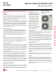
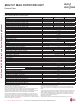
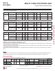
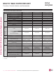
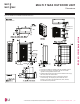
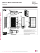
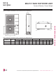
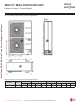
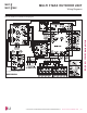
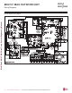
Table Of Contents

Multi F MAX Heat Pump Condensing
Units
General
A Multi F MAX multi-zone system is comprised of one heat pump
outdoor unit connected up to eight indoor units through a branch
distribution unit (BD) using a single refrigerant piping circuit, and
includes integrated controls supplied by LG. Factory-designed and
supplied Y-branches may be used as well.
The outdoor unit is internally assembled, wired, and piped from the
factory; all LG components are manufactured in a facility registered
to ISO 9001 and ISO 14001, set by the International Organization for
Standardization (ISO). The LG Multi F MAX multi-zone heat pump
system components comply with Underwriters Laboratories (UL)
1995 Heating and Cooling Equipment Standard for Safety. The units
are certified to AHRI 210 / 240.
Temperature Ranges
The heat pump outdoor units are capable of operating in cooling
mode from 14°F to 118°F ambient dry bulb (installing an optional
Low Ambient Wind Baffle Kit will allow operation down to -4°F in
cooling mode for Multi F MAX systems). The heat pump outdoor
units are capable of operating in heating mode from -4°F to +64°F
ambient wet bulb without additional low ambient controls.
Frame
Multi F MAX condensing unit case is constructed from pre-coated
metal that has been tested in accordance with ASTM B-117 salt
spray procedure for a minimum of 1,000 hours. Case has a remov-
able front panel to allow access to major components and control
devices, and legs to secure the unit during installation.
Refrigerant System
Multi F MAX systems have a single refrigerant circuit field piped with
a manufacturer-supplied BD unit(s) and Y-branches (if applicable) to
multiple (ducted, non-ducted or mixed) indoor units to effectively and
efficiently control the heating or cooling operation of the multi zone
system. All refrigerant lines from the outdoor unit to the BD unit(s)
and from the BD unit(s) to indoor units are field-installed and must
be insulated separately.
Multi F MAX systems use R410A refrigerant. The LMU481HV and
LMU541HV outdoor units are equipped with a refrigerant strainer,
check valves, oil separator, hot gas bypass valve, accumulator,
four-way reversing valve, electronic expansion valve(s) (EEV), high
side and low side refrigerant charging ports, and a service port.
The outdoor unit also includes sensors for suction temperature,
discharge temperature, high-pressure, low-pressure, heat exchanger
temperature, and outdoor temperature conditions. The LMU601HV
outdoor unit includes the components cited above (except hot gas
bypass valve) in addition to a sub-cooled heat exchanger, vapor
injection and vapor bypass circuit.
Refrigeration Oil Control
The outdoor unit has an oil separator to separate oil mixed with the
refrigerant gas during compression and return oil to the compressor.
The outdoor unit also has an oil injection mechanism to ensure a
consistent film of oil on all moving compressor parts at low speed.
Compressor
Multi F MAX condensing units
are equipped with one hermeti-
cally sealed, digitally controlled,
inverter driven R1 scroll com-
pressor that includes Teflon™
coated bearings. The inverter
motor is capable of providing
a modulation range of 10Hz
to 130Hz for LMU481HV and
LMU541HV, or 10Hz to 130Hz
(cooling) and 10Hz to 150Hz
(heating) for LMU601HV, with
control in 1Hz increments. The
compressor uses a factory-
charge of Polyvinyl Ether (PVE)
oil, and is mounted to avoid the
transmission of vibration.
Fan and Motors
The Multi F MAX outdoor unit includes two direct drive variable
speed propeller fans with Brushless Digitally Controlled (BLDC)
motor with a horizontal air discharge.
Fan blades are statically and dynamically balanced propeller fans
made of durable Acrylonitrile Butadiene Styrene (ABS) plastic, and
include a raised fan guard to limit contact with moving parts. The
motors have inherent overload protection, permanently lubricated
bearings, and a maximum speed up to 670 rpm for LMU481HV and
LMU541HV, or 750 rpm for LMU601HV. Multi F MAX outdoor unit
has a horizontal discharge airflow.
Outdoor Unit Coil
7KH RXWGRRU XQLW FRLOV DUH IDFWRU\EXLOW RI DOXPLQXP ¿QV PHFKDQL-
cally bonded on copper tubing. Coils have a minimum of two rows
for LMU481HV and LMU541HV, or three rows for LMU601HV, a
PLQLPXP RI ¿QV SHU LQFK DQG KDYH EHHQ IDFWRU\ SUHVVXUHWHVWHG
&RLO ¿QV DOVR KDYH D IDFWRU\ DSSOLHG FRUURVLRQUHVLVWDQW *ROG)LQ PD-
terial with hydrophilic coating that has been tested in accordance with
ASTM B-117 salt spray test procedure for a minimum of 1,000 hours.
Electrical
Multi F MAX outdoor unit have 208/230V, 1 phase, 60Hz electrical
power capable of operating within ±10% of the rated voltage.
Controls
Factory installed microprocessor controls in the outdoor unit, BD
unit(s), and indoor units perform functions to efficiently operate
the multi-zone system. System wiring must be installed in a tree
configuration from outdoor unit to BD unit(s) to indoor units through
four conductor power/transmission cable. The system is capable of
performing continuous operation, even when power is turned off to
an individual indoor unit.
0HFKDQLFDO6SHFL¿FDWLRQV
MULTI F MAX OUTDOOR UNIT
Figure 18: Multi F MAX
LMU481HV and LMU541HV
Outdoor Units.
MULTI F MAX OUTDOOR UNIT | 31
Multi F MAX Outdoor Unit Data
'XHWRRXUSROLF\RIFRQWLQXRXVSURGXFWLQQRYDWLRQVRPHVSHFL¿FDWLRQVPD\FKDQJHZLWKRXWQRWL¿FDWLRQ
©/*(OHFWURQLFV86$,QF(QJOHZRRG&OLIIV1-$OOULJKWVUHVHUYHG³/*´LVDUHJLVWHUHGWUDGHPDUNRI/*&RUS
MULTI
F
MAX
MULTI
F