
Multi F Engineering Manual
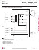
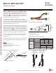
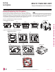
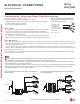
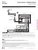
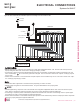
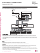
Table Of Contents

:LULQJ6SHFL¿FDWLRQV
ELECTRICAL CONNECTIONS
Figure 45: Typical Multi F System General Power / Communications
System Schematic.
Figure 46: Typical Multi F MAX System General Power / Communica-
tions System Schematic.
Power Supply
Circuit Breaker
Indoor Unit
Branch Distribution Unit
Ground Wiring
Outdoor Unit
Branch Distribution Unit
Indoor Units
Power Supply
Circuit Breaker
Ground Wiring
Outdoor Unit
Communication / Connection (Power) Cable Specifications
Never ground the shield of the communications cable to the indoor unit frame or other grounded entities of the building. Ground the communica-
tions cable shield only at the outdoor unit. Improperly grounding this cable can cause communications errors.
• Use a conduit for the communications / connection (power) cable from the outdoor unit to the indoor units and branch distribution unit(s).
Electrical interference my cause product malfunction.
• The communications / connection (power) cable from the outdoor unit to the indoor units / branch distribution unit(s) must be separated and
isolated from power wiring to the outdoor unit, computers, radio and television broadcasting facilities, as well as medical imaging equip-
ment. Electrical interference my cause product malfunction.
Figure 47: Typical Multi F / Multi F MAX Outdoor
and Indoor / Branch Distribution Unit Wiring and
Communications Cable Diagram.
Power Wiring, Ground,
Communication Cable
From Outdoor Unit
To Indoor Unit or from the
Outdoor Unit to the Branch
Distribution Unit
13/16”
GN/YL
GN/YL = (Ground, Yellow)
7/16" ± 1/8"
• Insulation material as required by local code.
• Rated for continuous exposure of temperatures up to 140°F.
• Firmly attach the cable; provide slack but secure in a way to prevent external forces
from being imparted on the terminal block.
• Wiring must be completed without splices.
Multi F Systems:
• Communication / connection (power) cable from the outdoor unit to the indoor unit must
use a minimum of 14 AWG, four (4) conductor, stranded, shielded or unshielded (if
shielded, it must be grounded to the chassis of the outdoor unit only), and must comply
with applicable local and national codes.
• Use of 14 AWG, four (4) conductor, stranded, shielded or unshielded wire is allowed for
lengths up to the published maximum pipe length, plus recommended slack at both ends.
Multi F MAX Systems:
• All communication / connection (power) cable from the outdoor unit to the branch distribution unit(s) must be a minimum of 14 AWG, four (4)
conductor, stranded, shielded or unshielded (if shielded, it must be grounded to the chassis of the outdoor unit only), and must comply with
applicable local and national codes.
• Communication / connection (power) cable from the branch distribution unit(s) to the indoor units must use a minimum of 14 AWG, four (4)
conductor, stranded, shielded or unshielded (if shielded, it must be grounded to the chassis of the outdoor unit only), and must comply with
applicable local and national codes.
• Use of 14 AWG, four (4) conductor, stranded, shielded or unshielded wire is allowed for lengths up to the published maximum pipe length,
plus recommended slack at both ends.
'XHWRRXUSROLF\RIFRQWLQXRXVSURGXFWLQQRYDWLRQVRPHVSHFL¿FDWLRQVPD\FKDQJHZLWKRXWQRWL¿FDWLRQ
©/*(OHFWURQLFV86$,QF(QJOHZRRG&OLIIV1-$OOULJKWVUHVHUYHG³/*´LVDUHJLVWHUHGWUDGHPDUNRI/*&RUS
56 | ELECTRICAL CONNECTIONS
Multi F and Multi F MAX Heat Pump System Engineering Manual
MULTI
F
MAX
MULTI
F