
Engineering Manual
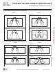
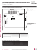
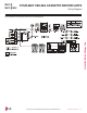
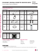

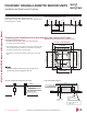
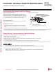
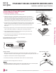
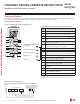
Table Of Contents
- Convergence of Technology, Innovation, Flexibility, & Style
- Unit Nomenclature
- Outdoor Unit Overview
- Indoor Unit Overview
- Controls and Options Overview
- Art Cool Mirror Indoor Units
- General Data / Specifications
- Dimensions
- Cooling Capacity Table
- Heating Capacity Table
- Acoustic Data
- Air Velocity and Temperature Distribution
- Refrigerant Flow Diagram
- Wiring Diagram
- Factory Supplied Parts and Materials
- Installation and Best Layout Practices
- Art Cool Gallery Indoor Units
- General Data / Specifications
- Dimensions
- Cooling Capacity Table
- Heating Capacity Table
- Acoustic Data
- Air Velocity and Temperature Distribution
- Refrigerant Flow Diagram
- Wiring Diagram
- Factory Supplied Parts and Materials
- Installation and Best Layout Practices
- Standard Wall-Mounted Indoor Units
- General Data / Specifications
- Dimensions
- Cooling Capacity Table
- Heating Capacity Table
- Acoustic Data
- Air Velocity and Temperature Distribution
- Refrigerant Flow Diagram
- Wiring Diagram
- Factory Supplied Parts and Materials
- Installation and Best Layout Practices
- Duct (Low Static) Indoor Units
- General Data / Specifications
- Dimensions
- Cooling Capacity Table
- Heating Capacity Table
- External Static Pressure
- Acoustic Data
- Refrigerant Flow Diagrams
- Wiring Diagram
- Factory Supplied Parts and Materials
- Installation and Best Layout Practices
- Duct (High Static) Indoor Units
- General Data / Specifications
- Dimensions
- Cooling Capacity Table
- Heating Capacity Table
- External Static Pressure / Acoustic Data
- Refrigerant Flow Diagrams
- Wiring Diagrams
- Factory Supplied Parts and Materials / Installation
- Installation and Best Layout Practices
- Four-Way Ceiling Cassette Indoor Units
- General Data / Specifications
- Dimensions
- Dimensions
- Cooling Capacity Table
- Heating Capacity Table
- Acoustic Data
- Air Velocity and Temperature Distribution
- Refrigerant Flow Diagram
- Wiring Diagram
- Factory Supplied Parts and Materials
- Installation and Best Layout Practices
- Vertical-Horizontal Indoor Units
- General Data / Specifications
- Dimensions
- Cooling Capacity Table
- Heating Capacity Table
- External Static Pressure
- Acoustic Data
- Refrigerant Flow Diagram
- Wiring Diagram
- Factory Supplied Parts and Materials
- Installation and Best Layout Practices
- Equipment Selection Procedure
- Building Ventilation Design Guide
- Placement Considerations
- Refrigerant Piping Design
- Design Guideline Summary
- Creating a Balanced System / Manual Layout Procedure
- LG Engineered Multi F MAX Y-Branch Kit
- Refrigerant Charge
- Installation & Layout Best Practices
- Refrigerant Piping System Layout
- Piping Insulation
- Condensate Drain Piping
- Y-Branch Kit
- Wiring Connections
- Power Wiring (208-230V) and Communications Cable Details
- Indoor Unit Group Control
- Acronyms

Figure 205:Checking the Drain Pump.
For Existing Ceilings
1. Use anchors when installing the indoor unit in an existing ceiling.
2. Ceiling height is shown on the side of the installation guide (template). Adjust the height of the unit accordingly. Adjust the clearance
before hanging the indoor unit.
3. Remove the temporary washer plate and position the indoor unit hanger brackets on the bolts. Secure with nuts and washers on the top
and bottom of the hanger brackets.
4. Ceiling-cassette indoor units are equipped with a built-in drain pump and float switch, therefore, the unit must be installed horizontally or
condensate will drip out and cause product malfunction. Measure the unit at each corner to verify that it is level.
5. Remove the installation guide (template).
For New Ceilings
1. Use a sunken insert, a sunken anchor, or any other field-supplied part to reinforce the
ceiling so that it can bear the weight of the indoor unit. Use a temporary washer plate
to more easily set up the unit suspension location.
2. Ceiling height is shown on the side of the installation guide (template). Adjust the
height of the unit accordingly. Adjust the clearance before hanging the indoor unit.
3. Refer to the installation guide (template) for the dimensions to the ceiling opening.
Match the center of the indoor unit (labeled) to the center indicated on the installation
guide.
4. Align the installation guide (template) with the label attached to the unit (affixing the
template to the unit if desired) to properly place the unit.
5. Remove the temporary washer plate and position the indoor unit hanger brackets
on the bolts. Secure with nuts and washers on the top and bottom of the hanger
brackets.
6. Ceiling-cassette indoor units are equipped with a built-in drain pump and float switch, therefore, the unit must be installed horizontally or
condensate will drip out and cause product malfunction. Measure the unit at each corner to verify that it is level.
7. Remove the installation guide (template).
Installation and Best Layout Practices
FOUR-WAY CEILING CASSETTE INDOOR UNITS
Flat washer for M10
(field supplied)
Flat washer for M10
(field supplied)
Hanging bolt
(W3/8 or M10)
Nut
(W3/8 or M10)
Nut
(W3/8 or M10)
Spring washer
(M10)
Figure 203:Hanging the Indoor Unit.
Installing the Drain System
• Drain piping must have downward gradient of at least 1/50 to 1/100; to prevent
reverse flow, slope should not be straight up and down.
• Do not damage the drain port on the indoor unit when connecting the field-supplied
drain piping.
• Drain piping specifications:
- Indoor Unit Drain Connection: 1-1/4 inch outside diameter.
- Field-Supplied Drain Piping: Polyvinyl chloride piping with 1-inch inside diameter
and pipe fittings.
1/50~
1/100
<27-9/16 inches
Pour Water
Drain Pump
Drain Pan
Flexible drain hose
(accessory)
Field-Installed
Drain Piping
Glue the Joint
Drain
Port
Drain Hose Connection
Use the clip (accessory)
Checking the Drain Pump
The unit uses a drain pump to remove condensate. The pump must be tested before the
system operates.
• Connect flexible drain hose to the field-installed drain piping; leave it as is until the test
is complete.
• Pour water into the flexible drain hose and check for leaks.
• After power wiring installation is complete, operate the drain pump to see if it sounds
and functions properly.
• After the test is complete, connect the flexible drain hose to the indoor unit drain port.
Figure 204: Indoor Unit Drain Piping.
CEILING-CASSETTE | 147
Four-Way Ceiling-Cassette
Due to our policy of continuous product innovation, some specications may change without notication.
©LG Electronics U.S.A., Inc., Englewood Cliffs, NJ. All rights reserved. “LG” is a registered trademark of LG Corp.
MULTI
F
MAX
MULTI
F