
Engineering Manual
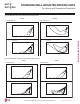
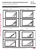
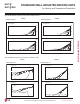
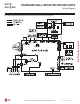

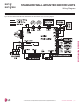
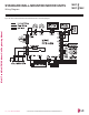
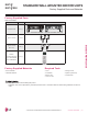
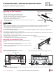
Table Of Contents
- Convergence of Technology, Innovation, Flexibility, & Style
- Unit Nomenclature
- Outdoor Unit Overview
- Indoor Unit Overview
- Controls and Options Overview
- Art Cool Mirror Indoor Units
- General Data / Specifications
- Dimensions
- Cooling Capacity Table
- Heating Capacity Table
- Acoustic Data
- Air Velocity and Temperature Distribution
- Refrigerant Flow Diagram
- Wiring Diagram
- Factory Supplied Parts and Materials
- Installation and Best Layout Practices
- Art Cool Gallery Indoor Units
- General Data / Specifications
- Dimensions
- Cooling Capacity Table
- Heating Capacity Table
- Acoustic Data
- Air Velocity and Temperature Distribution
- Refrigerant Flow Diagram
- Wiring Diagram
- Factory Supplied Parts and Materials
- Installation and Best Layout Practices
- Standard Wall-Mounted Indoor Units
- General Data / Specifications
- Dimensions
- Cooling Capacity Table
- Heating Capacity Table
- Acoustic Data
- Air Velocity and Temperature Distribution
- Refrigerant Flow Diagram
- Wiring Diagram
- Factory Supplied Parts and Materials
- Installation and Best Layout Practices
- Duct (Low Static) Indoor Units
- General Data / Specifications
- Dimensions
- Cooling Capacity Table
- Heating Capacity Table
- External Static Pressure
- Acoustic Data
- Refrigerant Flow Diagrams
- Wiring Diagram
- Factory Supplied Parts and Materials
- Installation and Best Layout Practices
- Duct (High Static) Indoor Units
- General Data / Specifications
- Dimensions
- Cooling Capacity Table
- Heating Capacity Table
- External Static Pressure / Acoustic Data
- Refrigerant Flow Diagrams
- Wiring Diagrams
- Factory Supplied Parts and Materials / Installation
- Installation and Best Layout Practices
- Four-Way Ceiling Cassette Indoor Units
- General Data / Specifications
- Dimensions
- Dimensions
- Cooling Capacity Table
- Heating Capacity Table
- Acoustic Data
- Air Velocity and Temperature Distribution
- Refrigerant Flow Diagram
- Wiring Diagram
- Factory Supplied Parts and Materials
- Installation and Best Layout Practices
- Vertical-Horizontal Indoor Units
- General Data / Specifications
- Dimensions
- Cooling Capacity Table
- Heating Capacity Table
- External Static Pressure
- Acoustic Data
- Refrigerant Flow Diagram
- Wiring Diagram
- Factory Supplied Parts and Materials
- Installation and Best Layout Practices
- Equipment Selection Procedure
- Building Ventilation Design Guide
- Placement Considerations
- Refrigerant Piping Design
- Design Guideline Summary
- Creating a Balanced System / Manual Layout Procedure
- LG Engineered Multi F MAX Y-Branch Kit
- Refrigerant Charge
- Installation & Layout Best Practices
- Refrigerant Piping System Layout
- Piping Insulation
- Condensate Drain Piping
- Y-Branch Kit
- Wiring Connections
- Power Wiring (208-230V) and Communications Cable Details
- Indoor Unit Group Control
- Acronyms

Due to our policy of continuous product innovation, some specications may change without notication.
©LG Electronics U.S.A., Inc., Englewood Cliffs, NJ. All rights reserved. “LG” is a registered trademark of LG Corp.
72 | STD. WALL-MOUNTED
Multi F and Multi F MAX Indoor Unit Engineering Manual
MULTI
F
MAX
MULTI
F
Figure 80:LSN120HSV4 Air Velocity and Temperature Distribution Charts.
Cooling Heating
Air velocity [ft/s]
Temperature [˚F]
2.5
4.1
3.3
4.9
1.6
77
75.2
73.4
8.9ft
6.6ft
4.0ft
0ft
0ft3.3ft6.6ft9.8ft13.1ft16.4ft
0ft3.3ft6.6ft9.8ft13.1ft16.4ft
8.9ft
6.6ft
4.0ft
0ft
Air velocity [ft/s]
Temperature [˚F]
2.5
4.1
3.3
4.9
1.6
82.4
84.2
86
8.9ft
6.6ft
4.0ft
0ft
0ft3.3ft6.6ft9.8ft13.1ft16.4ft
8.9ft
6.6ft
4.0ft
0ft
0ft3.3ft6.6ft9.8ft13.1ft16.4ft
Discharge angle:45° Discharge angle:50°
Air Velocity and Temperature Distribution
STANDARD WALL-MOUNTED INDOOR UNITS
Figure 81:LMN157HVT Air Velocity and Temperature Distribution Charts.
Cooling Heating
Temperature [°F]
1.6
1.6
4.9
6.6
8.2
9.8
3.3
70
68
64
9f t
7f t
3f t
0f t
16ft 13ft 10f t7ft 3f t
0f t
9f t
7f t
3f t
0f t
16ft 13ft 10f t7ft 3f t
0f t
Air velocity [ft/s]
Temperature [°F]
1.6
3.6
4.9
6.6
8.2
86
90
93
82
9f t
7f t
3f t
16ft 13ft 10f t7ft 3f t
0f t
9f t
7f t
3f t
0f t
0f t
16ft 13ft 10f t7ft 3f t
0f t
Air velocity [ft/s]
Discharge angle : 40° Discharge angle : 50°