
Multi F Engineering Manual


'XHWRRXUSROLF\RIFRQWLQXRXVSURGXFWLQQRYDWLRQVRPHVSHFL¿FDWLRQVPD\FKDQJHZLWKRXWQRWL¿FDWLRQ
©/*(OHFWURQLFV86$,QF(QJOHZRRG&OLIIV1-$OOULJKWVUHVHUYHG³/*´LVDUHJLVWHUHGWUDGHPDUNRI/*&RUS
52 | STD. WALL-MOUNTED
Multi F and Multi F MAX Indoor Unit Engineering Manual
MULTI
F
MAX
MULTI
F
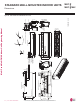
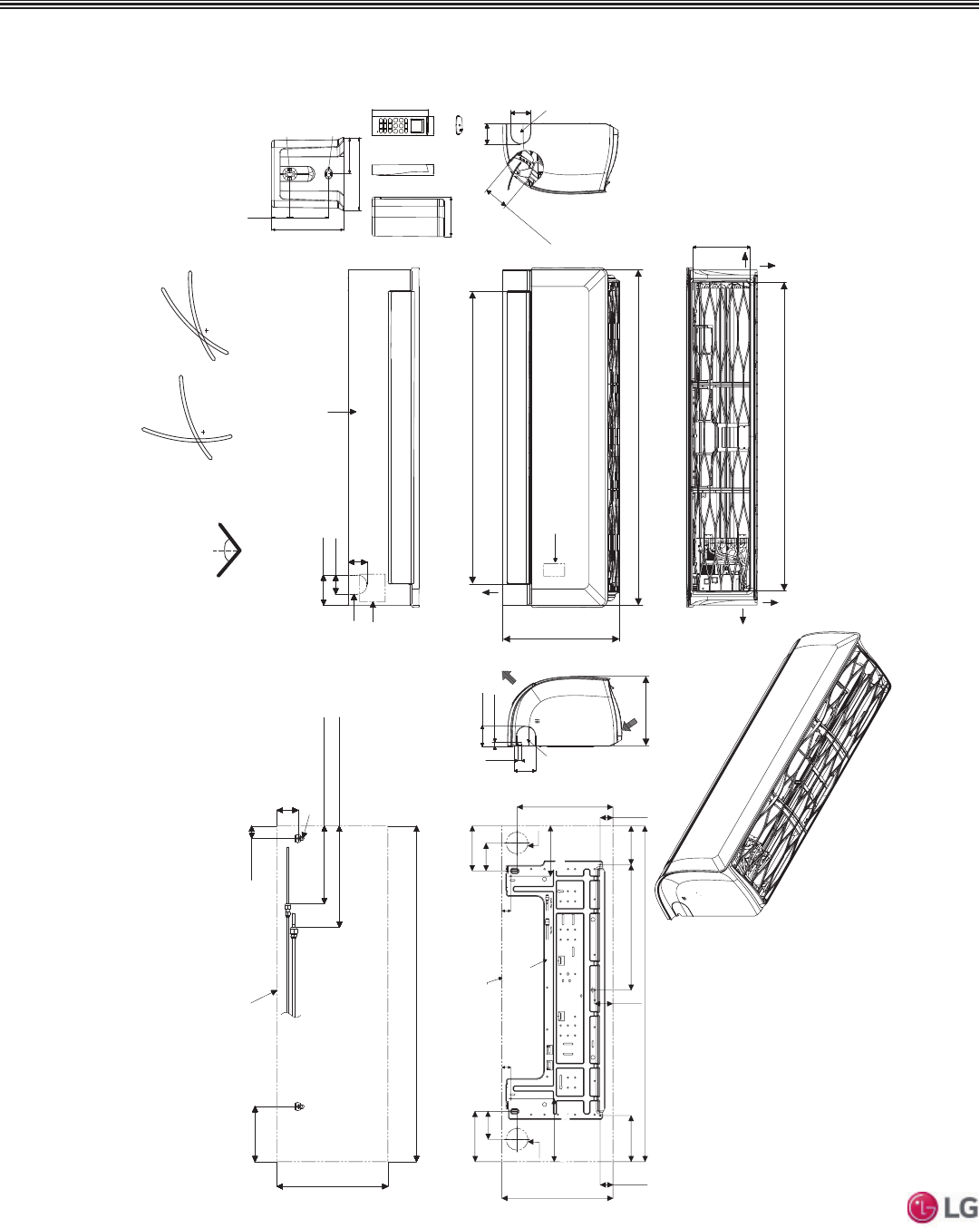
)LJXUH LSN180HSV5 and LMN249HVT Dimensions.
Dimensions
STANDARD WALL-MOUNTED INDOOR UNITS
Unit : Inch (mm)
[36-5/32 (918)]
Air Intake Hole
[6-11/16 (170)]
Air Intake Hole
[2-29/32 (74)]
Air Outlet Hole
Rear
39-9/32 (998)
2-1/4 (57)
2-7/32 (56)
3-17/32 (90)
Bottom
Air
Outlet
[34-11/32 (872)]
Air Outlet Hole
13-19/32 (345)
2-3/8 (60)
7/16(11)
Air Intake
8-9/32 (210)
13-19/32 (345)
39-9/32 (998)
6-15/32 (164)
1-15/32 (37)
2-15/32 (63)
In case of Left Side Piping
Unit Outline
Approx. 9-7/16 (240) to gas pipe
Approx. 6-5/16 (160) to liquid pipe
Connecting Gas/Liquid Pipe
2-3/8 (60)
2-3/8 (60)
Rear
Left
Right
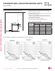
If airflow direction control is available,*
Cooling Heating
Up & Down Left & Right
50°
15°
20°
85°
45°
50°
39-9/32 (998)
2-23/32 (69)
14-11/16 (373)
5-13/32 (137)
2-3/32 (53)
13-19/32 (345)
Ø2-9/16 (65)
3-9/32 (83)
Unit Outline
Fixing the Installation Plate, Drilling Hole
1-1/16 (27)
5-29/32 (150)
4-17/32 (115)
Ø2-9/16 (65)
3-9/32 (83)
5-9/32 (134)
1-1/16 (27)
2-3/32 (53)
11-13/16 (300)
7/16 (11)
2-3/8 (60)
5-29/32 (150)5-29/32 (150)
7-13/32 (188)7-13/32 (188)
2-7/16 ( 61.5)
1-7/16 (33.5)
1-9/32 (32.7)
2-13/32
(61)
5-31/32 (152)
1/4 (6) x 1/8 (3)
1/8 (3) x 1/4 (6)
5/8 (15.3)
1-1/4 (31)
1-3/32 (50.2)
1-1/16 (26.2)
Refrigerant,
Drain Pipe
and Cable
Routing
Knock Out
Hole
Refrigerant,
Drain Pipe
and Cable
Routing
Knock Out
Hole
Display & Remote
Controller Signal
Receiver
Terminal Block for
Power Supply and
Communication
Refrigerant, Drain
Pipe and Cable
Routing Knock Out
Hole
Installation Plate
Drain Hose
Connection
Decoration Cover