
Multi F Engineering Manual
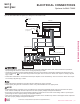
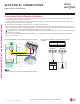
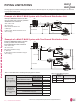
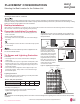
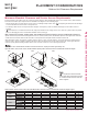
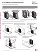
Table Of Contents

From Indoor Units to Remote Controllers
• Communication cable from indoor unit to remote controller(s) is to be 22 AWG, 3-conductor, twisted, stranded, unshielded. Wiring must
comply with all applicable local and national codes.
• If using the LG Controller / Extension cable and the length needs to be extended, the LG Extension Kit (sold separately) must be used. A
maximum of four (4) kits (up to 165 feet) can be used.
• Remote controllers have hardwired connections: SIG - 12V - GND (Comm.) terminals.
• Indoor unit controller connections depend on type of indoor unit being installed. Some indoor units use terminal block connections; other
indoor units use Mollex connections. See diagrams below for the two options. Refer to the wiring diagram schematic found in the indoor unit
itself, or to the indoor unit wiring diagrams in the Engineering Manuals for more information.
•
NEVER splice, cut, or extend cable length with field provided cable. Always include enough cable to cover distance between the indoor
unit and the remote controller.
• Set the indoor unit operating parameters using DIP switches, or by setting up the remote controller. Refer to the indoor unit installation
manuals for more details.
Cable connected to Zone Controller is the factory default connection.
Figure 53: One Example of Indoor Unit to Zone Controller Connection.
BACnet+
BACnet-
BACnet Common
Not used
Not used
Not used
Common
456
13 14 15
Typical Indoor Unit
Signal
12VDC
YL
RD
BK
CN-REMO
Indoor Unit
RD
BK
YL
Front
CN-REMO
RDBKYL
Back
Figure 54: Another Example of Indoor Unit to Zone Controller
Connection.
,QGRRU8QLWV&RQWUROOHUV
ELECTRICAL CONNECTIONS
'XHWRRXUSROLF\RIFRQWLQXRXVSURGXFWLQQRYDWLRQVRPHVSHFL¿FDWLRQVPD\FKDQJHZLWKRXWQRWL¿FDWLRQ
©/*(OHFWURQLFV86$,QF(QJOHZRRG&OLIIV1-$OOULJKWVUHVHUYHG³/*´LVDUHJLVWHUHGWUDGHPDUNRI/*&RUS
62 | ELECTRICAL CONNECTIONS
Multi F and Multi F MAX Heat Pump System Engineering Manual
MULTI
F
MAX
MULTI
F