
Multi F Outdoor Condenser Installation Manual

77
Final Installation Procedures
Due to our policy of continuous product innovation, some specifications may change without notification.
©LG Electronics U.S.A., Inc., Englewood Cliffs, NJ. All rights reserved. “LG” is a registered trademark of LG Corp.
MULTI
F
MAX
MULTI
F
Triple Evacuation Procedure
On Multi F MAX systems, after the leak / pressure check is complete, the triple evacuation
procedure must be performed to the refrigerant piping and all connected indoor units /
branch distribution units.
Do not just perform the deep evacuation procedure on Multi F
MAX systems. The deep evacuation procedure is insufficient to fully evacuate the extensive
piping systems on Multi F MAX products. Triple evacuation must be performed through the Schrader ports on the outdoor unit service ports.
7KHWULSOHHYDFXDWLRQSURFHGXUHLVDEHVWSUDFWLFHVUHFRPPHQGDWLRQIRU0XOWL)V\VWHPVEXWPDQGDWRU\IRU0XOWL)0$;V\VWHPV
)RUIDVWHUHYDFXDWLRQWKH6FKUDGHUFRUHFDQEHUHPRYHGDQGDQDX[LOLDU\VHUYLFHSRUWFDQXVHG0DNHVXUHWRUHLQVWDOOWKHRULJLQDO6FKUDGHUFRUH
before operating the system.
• Evacuate through both the liquid and gas (vapor) suction Schrader ports on the outdoor unit service ports.
• The outdoor unit service valves must remain closed and the stem head access caps tight.
Do not open the outdoor unit service valves
and release the factory refrigerant charge until trim charge is complete, and the system is ready to operate.
• Any field-installed ball valves in the refrigerant system (if used) must be open to ensure all piping is free and clear for evacuation on all
piping and connected indoor units / branch distribution units.
• Do not apply power to the system before performing the evacuation procedure. There is a possibility that the EEV valve will close and
LVRODWHVHFWLRQVRIWKHSLSLQJV\VWHPPDNLQJWKHHYDFXDWLRQSURFHGXUHLQFRQFOXVLYH
• Never perform evacuation using refrigerant.
• 8VHRQO\DYDFXXPSXPSWKDWFDQUHDFKPLFURQVYDFXXPUDWHGKRVHVRUFRSSHUWXELQJDQGDOHDNIUHHJDXJHPDQLIROGVHW
• 8VHRQO\QHZYDFXXPSXPSRLOIURPDSURSHUO\VHDOHGXQRSHQHGFRQWDLQHUDQGFKDQJHRLOLQSXPSEHIRUH(9(5<XVH
• Subsequent oil changes will be necessary after several hours of continuous operation; have extra oil on hand.
• Use a quality micron gauge in good operating order and install as far away from pump as possible.
Deep Evacuation Procedure, continued.
3. (YDFXDWHWRVWDWLFPLFURQOHYHOIRUDWOHDVWRQHKRXU
4. 0LFURQOHYHOPXVWUHPDLQIRUWZRKRXUV,IWKHYDFXXPJDXJHULVHVDQGVWRSV
the system could contain moisture; therefore, it will be necessary to repeat the steps of
vacuum break and drying.
5. $IWHUPDLQWDLQLQJWKHV\VWHPLQYDFXXPPLFURQIRUWZRKRXUVFKHFNLIWKH
vacuum gauge rises or not. If it doesn’t rise, then the system is properly evacuated.
6. Close manifold gauges.
7. Shut the valves before turning off and disconnecting the vacuum pump.
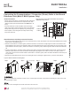
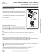
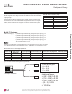
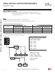
Figure 101: Evacuation Procedure Diagram.
Lo Hi
Vacuum Pump
Open
Open
Indoor Units
Outdoor Unit
Manifold Valve
Pressure
Gauge
Service Ports
Appearances will vary depending on model.
'HHS(YDFXDWLRQ7ULSOH(YDFXDWLRQ7HVWV
FINAL INSTALLATION PROCEDURES