
Multi F Engineering Manual


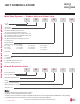

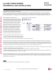


Table Of Contents

'XHWRRXUSROLF\RIFRQWLQXRXVSURGXFWLQQRYDWLRQVRPHVSHFL¿FDWLRQVPD\FKDQJHZLWKRXWQRWL¿FDWLRQ
©/*(OHFWURQLFV86$,QF(QJOHZRRG&OLIIV1-$OOULJKWVUHVHUYHG³/*´LVDUHJLVWHUHGWUDGHPDUNRI/*&RUS
10 | INTRODUCTION
Multi F and Multi F MAX Heat Pump System Engineering Manual
MULTI
F
MAX
MULTI
F
Qidu(combi) = Qodu(rated) x Qidu(rated)
ȉ4LGXUDWHG
Using the System Combination Tables
Multi F system combination tables illustrate how each indoor unit receives a percentage of total outdoor unit rated capacity. Allocation is
based on:
• Combinations of Non-Ducted Indoor Units
• Combinations of Ducted Indoor Units
• Combinations of Mixed Non-Ducted and Ducted Indoor Units
Multi F MAX system combination tables only show the total connected indoor unit capacity, but individual indoor unit capacity can be
calculated using the formula:
• A more accurate method to determine expected capacity would be to apply the outdoor unit’s corrected capacity instead of rated capacity.
• For allocated capacity information, see the combination tables in the “Multi F / Multi F MAX Combination Data Manual” on www.lghvac.com.
For performance data, see “Multi F / Multi F MAX Performance Data Manual” on www.lghvac.com.
Table 3: Multi F Outdoor Unit (Multiple Piping) to Indoor Unit Refrigerant Line Length Derates.
Piping Length (feet) Cooling Capacity (%) Heating Capacity (%)
7,000 Btu/h Indoor Unit Models
25.0 100.0 100.0
32.8 98.4 99.2
49.2 95.8 97.8
65.6 93.2 96.4
82.0 90.6 95.0
9,000 Btu/h Indoor Unit Models
25.0 100.0 100.0
32.8 98.0 99.0
49.2 94.8 97.4
65.6 91.6 95.8
82.0 88.4 94.2
12,000 Btu/h Indoor Unit Models
25.0 100.0 100.0
32.8 97.6 98.6
49.2 93.8 96.4
65.6 89.9 94.1
82.0 86.1 91.9
15,000 Btu/h Indoor Unit Models
25.0 100.0 100.0
32.8 97.2 98.2
49.2 93.0 95.4
65.6 88.8 92.6
82.0 84.6 89.8
18,000 Btu/h Indoor Unit Models
25.0 100.0 100.0
32.8 98.6 99.6
49.2 96.4 99.0
65.6 94.1 98.3
82.0 91.9 97.7
24,000 Btu/h Indoor Unit Models
25.0 100.0 100.0
32.8 98.2 99.2
49.2 95.4 98.0
65.6 92.4 96.6
82.0 89.6 95.4
Capacity Coefficient Factors
Refrigerant Line Length Derates
For air-cooled systems, a capacity correction factor may have to be applied to account for the length of the system’s refrigerant pipe. Rate of
change in capacity due to increased piping lengths is shown in the table below, and in the tables on the next page.
MANUAL EQUIPMENT
SELECTION PROCEDURE