
Multi F Engineering Manual
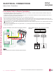
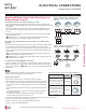
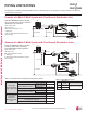


Table Of Contents

Device Connection Limitations
• The minimum number of connected and operating indoor units to Multi F / Multi F MAX systems is two, taking into consideration the
minimum combination ratio.
• The maximum number of indoor units for each Multi F / Multi F MAX heat pump systems is:
LMU183HV = 2 LMU243HV = 3 LMU303HV = 4 LMU363HV = 4 LMU481HV = 8 LMU541HV = 8 LMU601HV = 8
PIPING LIMITATIONS
One of the most critical elements of multi-zone systems is the refrigerant piping. The following pages list pipe length limits that must be
followed in the design of Multi F and Multi F MAX refrigerant pipe systems:
Table 35: Equivalent Piping Length for Elbows, Y-branches, and Branch
Distribution Units.
Max. 49.2 feet
Max. 24.6 feet
A
B
C
D
Example of a Multi F System
Example: LMU363HV outdoor unit with four (4)
indoor units connected.
ODU: Outdoor Unit.
IDU: Indoor Unit.
A, B, C, D: Pipes from Outdoor Unit to Indoor Unit.
Outdoor Unit
Minimum Length for Each Pipe
(ft.)
Maximum Piping Length to Each Indoor Unit (ft.)
Maximum Total Piping Length for Each
System (ft.)
ABCD
LMU183HV 9.8 82 82 - - 164.0
LMU243HV 9.8 82 82 - - 230.0
LMU303HV 9.8 82 82 82 82 246.1
LMU363HV 9.8 82 82 82 82 246.1
1
Kit contains two Y-branches: one for liquid and one for vapor.
Table 36: Multi F Outdoor Unit Refrigerant Piping System Limitations.
Component
Size (Inches)
1/4 3/8 1/2 5/8 3/4
Elbow (ft.)
0.5 0.6 0.7 0.8 1.2
Y-Branch Kit (ft., Multi F MAX systems
only)
1
1.6
Branch Distribution Unit (ft., Multi F
MAX systems only)
8.2
Field-supplied elbows are allowed as long as they are designed for
use with R410A refrigerant. The designer, however, must be cau-
tious with the quantity and size of fittings used, and must account for
the additional pressure losses in equivalent pipe length calculation
for each branch. The equivalent pipe length of each elbow must be
added to each pipe segment.
Using Refrigerant Components
For allocated capacity information, see the combination tables in the “Multi F / Multi F MAX Combination Data Manual” on www.lghvac.com. For
performance data, see “Multi F / Multi F MAX Performance Data Manual” on www.lghvac.com.
Following pages present Multi F / MAX piping limitations and are for illustrative purposes only. Designers are highly encouraged to use LATS when
designing Multi F / MAX systems.
'XHWRRXUSROLF\RIFRQWLQXRXVSURGXFWLQQRYDWLRQVRPHVSHFL¿FDWLRQVPD\FKDQJHZLWKRXWQRWL¿FDWLRQ
©/*(OHFWURQLFV86$,QF(QJOHZRRG&OLIIV1-$OOULJKWVUHVHUYHG³/*´LVDUHJLVWHUHGWUDGHPDUNRI/*&RUS
PIPING AND PLACEMENT | 65
Piping Limitations and Placement Considerations
MULTI
F
MAX
MULTI
F