
Multi F Engineering Manual
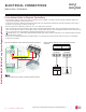
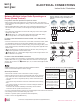

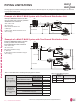
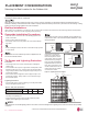
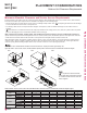
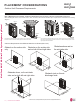
Table Of Contents

Multi F Outdoor Unit (18,000, 24,000, 30,000, and 36,000 Btu/h Capacities) Service Access and Allowable Clearances
Specific clearance requirements in the diagram below are for 18,000, 24,000, 30,000, 36,000 Btu/h capacities. The figure below shows the
overall minimum clearances that must be observed for safe operation and adequate airflow around the outdoor unit.
When placing the outdoor unit under an overhang, awning, sunroof or other “roof-like structure”, observe the clearance requirements (as
shown in Cases 1 and 2) for height in relation to the unit. To have successful service access to the outdoor unit, see the figure below for
minimum spacing. When installing multiple outdoor units, see Cases 4 and 5 for correct spacing requirements.
Figure 58: Multi F 18,000, 24,000, 30,000, and 36,000 Btu/h Capacity Outdoor Unit Service Access and Allowable Clearances Diagram.
Unit: Inch A B C D E F G
Case 1
Standard
12 24 - 12 - - -
Minimum
410-4--40
Case 2
Standard
--20----
Minimum
--14---40
Case 3
Standard
- - 20 12 - - -
Minimum
--144---
Case 4
Standard
---1224--
Minimum
---4879-
Case 5
Standard
-24-12- - -
Minimum
-10- 4 - - -
Table 40: Multi F 18,000, 24,000, 30,000, and 36,000 Btu/h Outdoor Unit Service Access and Allowable Clearances Diagram Legend.
Do not place the unit where animals
and/or plants will be in the path of the warm
air, or where the warm air and/or noise will
disturb neighbors.
If the outdoor unit is installed between standard and minimum clearances, capacity decreases approximately 10%.
Minimum Allowable Clearance and Service Access Requirements
Proper clearance for the outdoor unit coil is critical for proper operation. When installing the outdoor unit, consider service, inlet and outlet,
and minimum allowable space requirements as illustrated in the diagrams on the following pages.
• Include enough space for airflow and for service access. If installing multiple outdoor units, avoid placing the units where the discharge
of one unit will blow into the inlet side of an adjacent unit.
• If an awning is built over the unit to prevent direct sunlight or rain exposure, make sure that the discharge air of the outdoor unit isn’t
restricted.
•
No obstacles to air circulation around the unit; keep proper distances from ceilings, fences, floor, walls, etc. (Install a fence to prevent
pests from damaging the unit or unauthorized individuals from accessing it.)
A
B
D
G
C
G
C
D
E
D
D
B
B
F
1/16 inch
20 inches or less
Case 1
Case 4
Case 2 Case 3
Case 5
20 inches or less
PLACEMENT CONSIDERATIONS
2XWGRRU8QLW&OHDUDQFH5HTXLUHPHQWV
'XHWRRXUSROLF\RIFRQWLQXRXVSURGXFWLQQRYDWLRQVRPHVSHFL¿FDWLRQVPD\FKDQJHZLWKRXWQRWL¿FDWLRQ
©/*(OHFWURQLFV86$,QF(QJOHZRRG&OLIIV1-$OOULJKWVUHVHUYHG³/*´LVDUHJLVWHUHGWUDGHPDUNRI/*&RUS
PIPING AND PLACEMENT | 69
Piping Limitations and Placement Considerations
MULTI
F
MAX
MULTI
F