
Multi F Outdoor Condenser Installation Manual


70
MULTI F / MULTI F MAX Outdoor Unit Installation Manual
Due to our policy of continuous product innovation, some specifications may change without notification.
©LG Electronics U.S.A., Inc., Englewood Cliffs, NJ. All rights reserved. “LG” is a registered trademark of LG Corp.
MULTI
F
MAX
MULTI
F
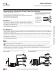
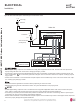
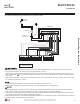
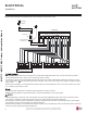
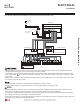
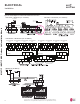
Figure 91: Detailed Diagrams of Outdoor Unit PCB Terminal Connections.
ELECTRICAL
,QVWDOODWLRQ
LMU183HV / LMU243HV (18 / 24 kBtu/h) LMU303HV / LMU363HV (30 / 36 kBtu/h)
250 V / T5 A
CN_POWER
BK WH BR BL
RD
BL
WCN_GND1
WCN_GND2
LMU601HV (60 kBtu/h)
LMU481HV / LMU541HV (48 / 54 kBtu/h)
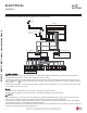
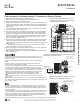
Indoor Unit Terminal Block
A Unit
Indoor Unit Terminal Block
B Unit
Indoor Unit Terminal Block
C Unit
Indoor Unit Terminal Block
D Unit
Indoor Unit Terminal Block
E Unit
Indoor Unit Terminal Block
F Unit
Indoor Unit Terminal Block
G Unit
Indoor Unit Terminal Block
H Unit
BD Unit (A)
BD Unit (A)
A Room B Room C Room D Room A Room B Room C Room D Room
BD Unit (B)
)B(tinUDB
1(L1) 2(L2) 3(A) 1(L1) 2(L2) 3(B) L1 L2
L(L1) N(L2) S L(L1) N(L2) S
1(L1) 2(L2) 3
L(L1) N(L2) S
1(L1) 2(L2) 3
L(L1) N(L2) S
1(L1) 2(L2) 3
L(L1) N(L2) S
1(L1) 2(L2) 3
L(L1) N(L2) S
1(L1) 2(L2) 3
L(L1) N(L2) S
1(L1) 2(L2) 3
L(L1) N(L2) S
1(L1) 2(L2) 3
L(L1) N(L2) S
1(L1) 2(L2) 3
L(L1) N(L2) S