
Multi F Engineering Manual
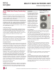

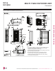
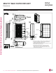

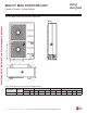
Table Of Contents

MULTI F MAX OUTDOOR UNIT
'LPHQVLRQV
Figure 20: LMU601HV External Dimensions.
Chassis code : U60A-B
54ïï»
49ñ»
13
ñï»
(1»๛)
ï»๛
3ïñ»๛
37ïñ»
3ïເ»
24ïñ»๛
(3»)
(6ñï»)
23ðເ»
15ïï»
14ñ»๛
6ï» 24ïñ»
11ï»
10ເ»
4ñ»
1»๛
16ñ»
3ï»
9ðເ»
27ïñ»
5ïñ»๛
7
5ñï»
3»
1. Unit must be installed in compliance with the installation manual.
2. Unit must be grounded in accordance with the local or state
regulations and applicable national codes.
3. All field-supplied electrical components and materials must comply
with local, state, and national codes.
4. Electrical characteristics must be considered for electrical
work and design. The capacity of power cable and circuit
breaker for the outdoor unit must follow local, state, national,
and manufacturer requirements.
Notes:
Handle
Liquid Pipe
Connection
(Flare)
Handle
Vapor Pipe
Connection
(Flare)
Power Wiring /
Communication
Cable Access
Holes
Air Outlet
'XHWRRXUSROLF\RIFRQWLQXRXVSURGXFWLQQRYDWLRQVRPHVSHFL¿FDWLRQVPD\FKDQJHZLWKRXWQRWL¿FDWLRQ
©/*(OHFWURQLFV86$,QF(QJOHZRRG&OLIIV1-$OOULJKWVUHVHUYHG³/*´LVDUHJLVWHUHGWUDGHPDUNRI/*&RUS
36 | MULTI F MAX OUTDOOR UNIT
Multi F and Multi F MAX Heat Pump System Engineering Manual
MULTI
F
MAX
MULTI
F