ENGLISH FRANCAIS ESPAÑOL INSTALLATION MANUAL AIR CONDITIONER • Please read this installation manual completely before installing the product. • Installation work must be performed in accordance with the national wiring standards by authorized personnel only. • Please retain this installation manual for future reference after reading it thoroughly. TYPE : Ceilling Concealed Duct http://www.lghvac.com www.lg.
TIPS FOR SAVING ENERGY ENGLISH TIPS FOR SAVING ENERGY Here are some tips that will help you minimize the power consumption when you use the air conditioner. You can use your air conditioner more efficiently by referring to the instructions below: • Do not cool excessively indoors. This may be harmful for your health and may consume more electricity. • Block sunlight with blinds or curtains while you are operating the air conditioner.
IMPORTANT SAFETY INSTRUCTIONS 3 READ ALL INSTRUCTIONS BEFORE USING THE APPLIANCE. Always comply with the following precautions to avoid dangerous situations and ensure peak performance of your product ! WARNING It can result in serious injury or death when the directions are ignored ! CAUTION It can result in minor injury or product damage when the directions are ignored ! WARNING • Installation or repairs made by unqualified persons can result in hazards to you and others.
IMPORTANT SAFETY INSTRUCTIONS ENGLISH • Make sure that a sekparate power supply circuit is provided for this unit and that all electrical work is carried out by qualified personnel according to local laws and regulations and this installation manual. An insufficient power supply capacity or improper electrical construction may lead to electric shocks or fire. • Be sure to switch off the unit before touching any electrical parts.
TABLE OF CONTENTS ENGLISH TABLE OF CONTENTS 2 TIPS FOR SAVING ENERGY 3 IMPORTANT SAFETY INSTRUCTIONS 6 INSTALLATION PLACES 21 OPTIONAL OPERATION 21 22 23 24 25 THE INDOOR UNIT INSTALLATION 10 11 12 Combination indoor units Flaring work Connection of piping - Indoor, Outdoor, BD Unit Plumbing materials and storage methods Indoor Unit Drain Piping Drain test Heat insulation Wiring Connection Connection method of the connecting cable(Example) 12 15 15 16 16 16 18 REMOTE CONTROLLER INSTALLATION In
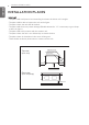
INSTALLATION PLACES Indoor unit - The place shall easily bear a load exceeding four times the indoor unit’s weight. - The place shall be able to inspect the unit as the figure. - The place where the unit shall be leveled. - The place shall allow easy water drainage.(Suitable dimension “H” is necessary to get a slope to drain as figure.) - The place shall easily connect with the outdoor unit. - The place where the unit is not affected by an electrical noise.
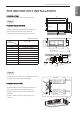
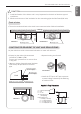
THE INDOOR UNIT INSTALLATION ENGLISH THE INDOOR UNIT INSTALLATION Installation of Unit Install the unit above the ceiling correctly. A B Position of suspension Bolt C E filter Case 1 body D - Apply a joint-canvas between the unit and duct to absorb unnecessary vibration. - Apply a filter Accessory at air return hole. F Joint canvas (G) Main duct 24 k / 36 k 1,232 (48-1/2) 1,182 (46-17/32) 355 (13-31/32) 45.
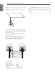
THE INDOOR UNIT INSTALLATION ENGLISH - Select and mark the position for fixing bolts. - Drill the hole for set anchor on the face of ceiling. - Insert the set anchor and washer onto the suspension bolts for locking the suspension bolts on the ceiling. - Mount the suspension bolts to the set anchor firmly. - Secure the installation plates onto the suspension bolts (adjust level roughly) using nuts, washers and spring washers.
THE INDOOR UNIT INSTALLATION 1 Install declination of the indoor unit is very important for the drain of the duct type air conditioner. 2 Minimum thickness of the insulation for the connecting pipe shall be 5mm(3/16 inch). Front of view • The unit must be declined to the drain hose connected when finished installation.
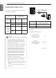
THE INDOOR UNIT INSTALLATION ENGLISH Combination indoor units BD unit (PMBD3641) The indoor units connectable to the outdoor unit are shown below Indoor Unit Outdoor Unit (Btu/h class) Capacity (Btu/h class) 36k 54k Vertical AHU 24k O O 36k X O Ceiling Concealed Duct (High Static) 24k O O 36k X O Type ! NOTE 1. The total capacity(in Btu/h unit) of connected indoor unit models represents the total sum of the figures expressed in the indoor model name. 2.
THE INDOOR UNIT INSTALLATION ENGLISH Flaring work 11 Flare nut Copper tube Main cause of gas leakage is defect in flaring work. Carry out correct flaring work in the following procedure. 1 Cut the pipes - Use the accessory piping kit or the pipes purchased locally. - Measure the distance between the indoor and the outdoor unit. - Cut the pipes a little longer than measured distance. - Cut the cable 1.5m(4.9ft) longer than the pipe length.
THE INDOOR UNIT INSTALLATION ENGLISH Connection of piping - Indoor, Outdoor, BD Unit Align the center of the piping and sufficiently tighten the flare nut by hand. Refrigerant Connections Pipe size Capacity (kBtu/h) Liquid Gas 24 1/4 (Ø6.35) 1/2 (Ø12.7) 36 3/8 (Ø9.52) 5/8 (Ø15.
THE INDOOR UNIT INSTALLATION 13 Pipe must be able to obtain the specified thickness and should be used with low impurities. Also when handling storage, pipe must be careful to prevent a fracture, deformity and wound. Should not be mixed with contaminations such as dust, moisture.
THE INDOOR UNIT INSTALLATION Welding, as when heating without nitrogen substitution a large amount of the oxide film is formed on the internal piping. The oxide film is a caused by clogging EEV, Capillary, oil hole of accumulator and suction hole of oil pump in compressor. It prevents normal operation of the compressor. In order to avoid this problem, Welding should be done after replacing air by nitrogen gas. When welding plumbing pipe, the work is required.
THE INDOOR UNIT INSTALLATION 15 Upward routing not allowed Pipe clamp Indoor unit Maintenance drain port 1 Remove the Air Filter. - Drain piping must have down-slope (1/50 to 1/100): be sure not to provide up-and-down slope to prevent reversal flow. - During drain piping connection, be careful not to exert extra force on the drain port on the indoor unit. - The outside diameter of the drain connection on the indoor unit is 32 mm(1-1/4 inch).
THE INDOOR UNIT INSTALLATION ENGLISH Heat insulation 1 1 Use the heat insulation material for the refrigerant piping which has an excellent heat-resistance (over 120°C). 2 Precautions in high humidity circumstance: This air conditioner has been tested according to the "KS Standard Conditions with Mist" and confirmed that there is not any default. However, if it is operated for a long time in high humid atmosphere (dew point temperature: more than 23°C), water drops are liable to fall.
THE INDOOR UNIT INSTALLATION 17 ENGLISH ! CAUTION The power connecting cable between the outdoor and indoor units must comply with the following specifications: NRTL Recognized (for example, UL or ETL recognized and CSA certified). AWG 18-4 is the minimum recommended wire size, however, the selected conductors must comply with local codes and be suitable for installation in wet locations.
REMOTE CONTROLLER INSTALLATION ENGLISH REMOTE CONTROLLER INSTALLATION Please fix tightly using provided screw after placing remote controller setup board on the place where you like to setup. - Please set it up not to bend because poor setup could take place if setup board bends. Please set up remote controller board fit to the reclamation box if there is a reclamation box. Can set up Wired remote controller cable into three directions.
REMOTE CONTROLLER INSTALLATION 19 Please check if connector is normally connected. FAN SPEED Indoor Unit side TEMP OPER MODE Connecting cable Please use extension cable if the distance between wired remote controller and indoor unit is more than 10m. Please fix remote controller upper part into the setup board attached to the surface of the wall, as the picture below, and then, connect with setup board by pressing lower part.
REMOTE CONTROLLER INSTALLATION ENGLISH Wired remote controller installation Since the room temperature sensor is in the remote controller, the remote controller box should be installed in a place away from direct sunlight, high humidity and direct supply of cold air to maintain proper space temperature. Install the remote controller about 5ft(1.5m) above the floor in an area with good air circulation at an average temperature.
OPTIONAL OPERATION 21 ENGLISH OPTIONAL OPERATION Installer Setting - Test Run Mode After installing the product, you must run a Test Run mode. For details related to this operation, refer to the product manual. OPER MODE pressing the button and 1 When button simultaneously for more than 3 seconds, the system will be entered into the installer setting mode. - After entering into the installer setting mode, select the test run mode code OPER value by pressing the MODE button.
OPTIONAL OPERATION ENGLISH Installer Setting - Setting Address of Central Control It's the function to use for connecting central control. Please refer to central controller manual for the details. OPER MODE pressing the button and button 1 When simultaneously for more than 3 seconds, the system will be entered into the installer setting mode. - After entering into the installer setting mode, select the central control address setting code OPER value by pressing the MODE button.
OPTIONAL OPERATION 23 ENGLISH Installer Setting - Thermistor This is the function to select the temperature sensor to judge the room temperature. OPER MODE pressing the button and 1 When button simultaneously for more than 3 seconds, the system will be entered into the installer setting mode. - After entering into the installer setting mode, select the thermistor sensor OPER setting code value by pressing the MODE button.
OPTIONAL OPERATION ENGLISH Installer Setting - Group Setting It is a function for settings in group control, or 2-remote controller control. OPER MODE pressing the button and button 1 When simultaneously for more than 3 seconds, the system will be entered into the installer setting mode. - After entering into the installer setting mode, select the ceiling height setting code value by pressing the oper-mode button.
OPTIONAL OPERATION 25 ENGLISH Installer Setting - Celsius / Fahrenheit Switching This function is used for switching the display between Celsius and Fahrenheit. (Optimized only for U.S.A) OPER MODE pressing the button and button 1 When simultaneously for more than 3 seconds, the system will be entered into the installer setting mode. - After entering into the installer setting mode, select the ceiling height setting code value by pressing the oper-mode button.
HOW TO SET E.S.P? ENGLISH HOW TO SET E.S.P? Installer Setting - E.S.P. This is the function that decides the strength of the wind for each wind level and because this function is to make the installation easier. • If you set ESP incorrectly, the air conditioner may malfunction. • This setting must be carried out by a certificated-technician. OPER MODE pressing the button and 1 When button simultaneously for more than 3 seconds, the system will be entered into the installer setting mode.
HOW TO SET E.S.P? 27 Capacity Step CFM 2.5(0.1) 4(0.15) 6(0.23) 8(0.31) 10(0.39) 12(0.47) 14(0.55) 16(0.62) 18(0.70) 20(0.
DIP SWITCH SETTING ENGLISH DIP SWITCH SETTING ON 1 2 3 4 5 6 7 8 Indoor PCB Function Description Setting Off SW3 Group Control Selection of Master or Slave Setting On Default Master Slave Off SW4 Dry Contact Mode Selection of Dry Contact Mode Wired/Wireless remote controller Selection of Manual or Auto operation Mode Auto Off SW5 Installation Fan continuous operation Continuous operation Removal Working Off