
Ceiling Cassette Installation Manual


3
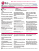
Typical Cassette Unit Installation
Installing the Indoor Unit
Mounting the IDU Chassis
• The ceiling should be strong and solid enough to prevent indoor unit vibration.
• Install the unit with a slight slope towards the drainage point to ensure condensate drains
easily.
• Select and mark the areas where the hanging bolts should be placed.
WARNING
The threaded rod hangers (bolts) and hardware must be securely tightened to prevent the
unit from falling from its installation location.
There is a risk of personal injury or death from falling equipment.
• Drill the holes and install the hanging bolts (threaded rods).
• Position the IDU and secure to the hanging bolts. Use a level to ensure the IDU is level with
a slight slope to the drainage point.
Flat washer for M10
(accessory)
Flat washer for M10
(accessory)
Hanging bolt
(W3/8 or M10)
Nut
(W3/8 or M10)
Nut
(W3/8 or M10)
Spring washer
(M10)
Drill Holes for Threaded Rods
Hang Indoor Unit on Threaded Rods
Connecting Refrigerant Pipes
Refrigerant Pipe Connections
Indoor units come with flare type connections. It is the installer’s option to use the flare fittings provided or braze the indoor unit to the
refrigerant piping system.
Flare Fittings
• All unit flare fittings are 45° and are rated for high-pressure R410A refrig-
erant.
• Properly form all flare fittings using best practices.
• Place a drop of PVE oil on the outside of flare fitting before tightening.
Note:
Multi V refrigeration system components contain very small capillary tubes, small
orices, electronic expansion valves, oil separators, and heat exchangers that can
easily become blocked.
Note:
• Do not use any other type of oil (including traditional POE refriger-
ation oil) as a lubricant. Failure to follow this procedure may lead to
restrictions in the refrigeration components.
• Do not over-tighten flare nuts. Excessive tightening will cause
fittings to crack.
Insulate Refrigerant Pipes
Sufficiently insulate all cold surfaces to prevent moisture forming. All pipes must be insulated and each pipe must be separately
wrapped. Use field-provided one-half (1/2) inch thick (or thicker) closed-cell insulation. The thickness may need to be increased
based on ambient conditions and local codes.
Wrap all refrigerant and condensate piping. Glue all insulation joints with no air gaps between insulation segments, and between
insulation segments and the unit case. Ensure insulation material fits snugly against the refrigeration pipe with no air space be-
tween the pipe surface and the surrounding insulation.
Protect insulation inside hangers and supports with a second insulation layer. Ensure insulation on all pipe passing through pipe
hangers, inside conduit, and/or sleeves is not compressed.
Typical Refrigerant Line Flare Fitting Insulation Detail
No Clearance
Overlap Insulation Where the
Port and the Piping Meet
Insulation for Indoor Unit Port
(Field Supplied)
Insulation for Refrigerant
Piping (Field Supplied)
Insulation Clip (Field Supplied)
Brazing
• Use a dry nitrogen purge operating at a minimum pressure of three (3) psig
and maintain a steady flow.
• Use a 15% silver phosphorous copper brazing alloy to avoid overheating and
produce good flow.
• Protect isolation valves, electronic expansion valves, and other heat-sensi-
tive components from excessive heat with a wet rag or heat barrier spray.
Set screw (4)
for paper pattern
Paper pattern
Ceiling board
Ceiling
Distance of bolt
from bracket: 1-1/2
Open ceiling board
along outer edge
of paper pattern
Ceiling Cassette
Chassis
Ceiling board
Distance between chassis
and ceiling surface:
19/32 for TM/TN/TP chassis
1-7/32 to 1-11/32 for TQ/TR chassis
Unit: inch
5-7/8 (TM/TN/TP/TQ/TR chassis)
3-9/16 (TL chassis)
2-3/16 (TU/TT chassis)