
LGRED Heat General Service Manual

Part 5. Trouble Shooting
- 60 -
Copyright ©2017 LG Electronics. Inc. All right reserved.
Only for training and service purposes
LGE Internal Use Only
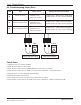
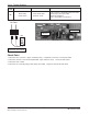
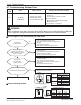
▶18,24,30kBtu/h class
25 26 27 29
30
32
33
P
W V U
NwNvNu
33
32
30
29
27
26
25
U1
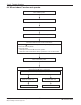
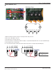
IPM Check Point
1. Wait until inverter PCB DC voltage is discharged after main power off.
2. Pull out V, V, W COMP connector.
3. Set multi tester to resistance mode.
4.
If the value between P and N terminal of IPM is short(0Ω) or open(hundreds MΩ), PCB needs to be replaced.(IPM damaged)
5. Set the multi tester to diode mode.
6. In case measured value is different from the table, PCB needs to be replaced.(PCB damaged).
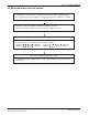
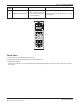
27 26 25 24 23 22 21
P U V W Nu Nv Nw
0.4 ~ 0.6 V
27 26 25 24 23 22 21
P U V W Nu Nv Nw
0.4 ~ 0.6 V
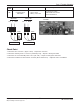
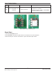
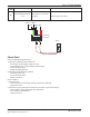
PFC_IPM check
U, V, W ‘ R S T