MULTI F MULTI F MAX INDOOR UNIT ENGINEERING MANUAL Low Wall Console Vertical-Horizontal Air Handling Units Art CoolTM Mirror Wall-Mounted Four-Way Ceiling Cassette Ceiling-Concealed Duct Indoor Units for Multi-Zone Heat Pump Systems 7,000 to 36,000 Btu/h Art CoolTM Gallery Wall-Mounted
PROPRIETARY DATA NOTICE This document, as well as all reports, illustrations, data, information, and other materials are the property of LG Electronics U.S.A., Inc., and are disclosed by LG Electronics U.S.A., Inc., only in confidence. This document is for design purposes only. For continual product development, LG reserves the right to change specifications without notice. ©LG Electronics Inc.
MULTI F MULTI F MAX TABLE OF CONTENTS Functions, Controls and Options Overview.........................................................................6 External Static Pressure................................................................... 100 Acoustic Data................................................................................... 101 Refrigerant Flow Diagram................................................................. 102 Wiring Diagram...................................................
CONVERGENCE OF TECHNOLOGY, INNOVATION, FLEXIBILITY, & STYLE Multi F and Multi F MAX Indoor Unit Engineering Manual About LG Electronics, Inc. LG Electronics is a global leader and technology innovator in consumer electronics, mobile communications, and home appliances. LG Electronics comprises five business units—Home Entertainment, Mobile Communications, Air Conditioning, Business Solutions, and Home Appliance.
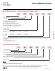
MULTI F MULTI F MAX UNIT NOMENCLATURE Multi-Zone Systems — Indoor Units and Outdoor Units L M CN 07 8 HV BD 36 2 0 L = LG Type: M = Multi-Zone Component: AN: Art Cool™ Wall-Mounted Indoor Unit N: Standard Wall-Mounted Indoor Unit QN: Low Wall Console Indoor Unit CN: Four-Way Ceiling-Cassette Indoor Unit DN: Ceiling-Concealed Duct (Low Static) Indoor Unit HN: Ceiling-Concealed Duct (High Static) Indoor Unit VN: Vertical-Horizontal Air Handling Indoor Unit U: Outdoor Unit 30 = 30,000 36 = 36,000
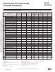
MULTI F MULTI F MAX FUNCTIONS, CONTROLS AND OPTIONS OVERVIEW Table 1: Indoor Units—Functions, Controls and Options.
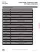
MULTI F MULTI F MAX FUNCTIONS, CONTROLS AND OPTIONS OVERVIEW Table 2: Indoor Unit Accessories Overview. Model No. Description Due to our policy of continuous product innovation, some specifications may change without notification. ©LG Electronics U.S.A., Inc., Englewood Cliffs, NJ. All rights reserved. “LG” is a registered trademark of LG Corp.
Multi F and Multi F MAX Indoor Unit Engineering Manual MULTI F MULTI F MAX 8 | INTRODUCTION Due to our policy of continuous product innovation, some specifications may change without notification. ©LG Electronics U.S.A., Inc., Englewood Cliffs, NJ. All rights reserved. “LG” is a registered trademark of LG Corp.
ART COOL MIRROR INDOOR UNIT DATA ™ “Mechanical Specifications” on page 10 “General Data / Specifications” on page 11 “Dimensions” on page 12 “Cooling Capacity Table” on page 14 “Heating Capacity Table” on page 16 “Acoustic Data” on page 17 “Air Velocity and Temperature Distribution” on page 18 “Refrigerant Flow Diagram” on page 19 “Wiring Diagram” on page 20 “Factory Supplied Parts and Materials” on page 21 “Installation and Best Layout Practices” on page 22
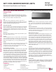
MULTI F MULTI F MAX ART COOL MIRROR INDOOR UNITS Mechanical Specifications and Features ART COOL Mirror Wall-Mounted Indoor Units Figure 1: Multi F Art Cool Mirror Wall-Mounted Indoor Unit. General Multi F and Multi F MAX Indoor Unit Engineering Manual All LG indoor units are factory assembled, wired, piped, and provided with a control circuit board, fan, and motor. ART COOL Mirror Wall-Mounted indoor units have a sound rating no higher than 44 dB(A) as tested per KSA0701 ISO Standard 3745.
MULTI F MULTI F MAX ART COOL MIRROR INDOOR UNITS General Data / Specifications Table 3: Multi F Art Cool Mirror Indoor Unit General Data. Model Name Nominal Cooling Capacity (Btu/h) 1 Nominal Heating Capacity (Btu/h) 1 LAN090HSV5 LAN120HSV5 LAN180HSV5 9,000 12,000 18,000 10,900 13,600 21,600 Operating Range Cooling (°F WB) Heating (°F DB) 57-77 59-81 Fan Type Cross Flow Motor Output (W) x Qty. 30 x 1 Motor/Drive 60.
Refrigerant, Drain Pipe and Cable Knock Out Hole 5/16 (8) Multi F and Multi F MAX Indoor Unit Engineering Manual Dimensions Unit : inch (mm) Rear Right 7-9/16 (192) Air Intake Air Outlet Drain Hose Connection Place a Level on Raised Tab C Type : 16.5 Attaching the Installation Plate, Drilling Hole C Type C Type : 3.9 32-15/16 (837) Unit Outline Connecting Gas/Liquid Pipe Ø2-9/16” Ø2-9/16" 7.6 5-3/16 (132) In Case of Left Side Piping C Type : 5.3 Installation Plate C Type : 16.
ART COOL MIRROR INDOOR UNITS Dimensions MULTI F MULTI F MAX Figure 3: LAN180HSV5 Dimensions. Unit : inch (mm) Display & Remote Controller Signal Receiver Signal 50° Rear Right Bottom Air Outlet 8-11/32 (212) Air Intake 7/16 (11) 2-3/8 (60) Terminal Block for Power Supply and Communication Refrigerant, Drain Pipe and Cable Knock Out Hole Refrigerant, Drain Pipe and Cable Knock Out Hole Place a Level on Raised Tab C Type: 19.8 Measuring Tape 39-9/32 (998) Measuring Tape Hanger Ø2-9/16" 3.
MULTI F MULTI F MAX ART COOL MIRROR INDOOR UNITS Cooling Capacity Table Table 4: Multi F Art Cool Mirror Indoor Units Cooling Capacity Table. Multi F and Multi F MAX Indoor Unit Engineering Manual Model No. / Air Nominal Capacity Outdoor Temp. of Indoor Unit (°F DB) (Btu/h) LAN090HSV5 9,000 LAN120HSV5 12,000 14 20 25 30 35 40 45 50 55 60 65 70 75 80 85 90 95 100 105 110 115 118 122 14 20 25 30 35 40 45 50 55 60 65 70 75 80 85 90 95 100 105 110 115 118 122 68 / 57 TC SHC 8.82 8.82 8.81 8.80 8.80 8.
MULTI F MULTI F MAX ART COOL MIRROR INDOOR UNITS Cooling Capacity Table Table 5: Multi F Art Cool Mirror Indoor Units Cooling Capacity Table (continued). Model No. / Air Nominal Capacity Outdoor Temp. of Indoor Unit (°F DB) (Btu/h) LAN180HSV5 18,000 17.65 17.63 17.62 17.60 17.59 17.58 17.56 17.55 17.54 17.52 17.51 17.50 17.08 16.66 16.24 15.82 15.37 14.99 14.62 14.24 13.87 13.65 13.57 12.33 12.43 12.52 12.62 12.71 12.81 12.90 13.00 13.10 13.19 13.29 13.38 13.16 12.93 12.70 12.46 12.33 12.00 11.67 11.
MULTI F MULTI F MAX ART COOL MIRROR INDOOR UNITS Heating Capacity Table Table 6: Multi F Art Cool Mirror Indoor Units Heating Capacity Table. Multi F and Multi F MAX Indoor Unit Engineering Manual Model No. / Nominal Capacity of Indoor Unit (Btu/h) Outdoor Air Temp. °F DB °F WB 61 TC 0 5 10 17 20 25 30 35 40 45 47 50 55 60 63 68 0 5 10 17 20 25 30 35 40 45 47 50 55 60 63 68 0 5 10 17 20 25 30 35 40 45 47 50 55 60 63 68 -0.4 4.5 9 15 19 23 28 32 36 41 43 46 51 56 59 64 -0.4 4.
MULTI F MULTI F MAX ART COOL MIRROR INDOOR UNITS Acoustic Data Figure 4: Sound Pressure Level Measurement Location. 3.3 ft. • Measurement taken 2.6′ below the bottom of the unit and at a distance of 3.3′ from face of unit. • Measurements taken with no attenuation and units operating at full load normal operating condition. • Sound level will vary depending on a range of factors such as construction (acoustic absorption coefficient) of particular area in which the equipment is installed.
MULTI F MULTI F MAX ART COOL MIRROR INDOOR UNITS Air Velocity and Temperature Distribution Figure 6: LAN090HSV5 and LAN120HSV5 Air Velocity and Temperature Distribution Charts. Multi F and Multi F MAX Indoor Unit Engineering Manual Cooling Heating Figure 7: LAN180HSV5 Air Velocity and Temperature Distribution Charts. Cooling 18 | ART COOL MIRROR Due to our policy of continuous product innovation, some specifications may change without notification. ©LG Electronics U.S.A., Inc.
MULTI F MULTI F MAX ART COOL MIRROR INDOOR UNITS Refrigerant Flow Diagram Figure 8: Art Cool Mirror Indoor Unit Refrigerant Flow Diagram. Th2 Vapor pipe connection port (flare connection) Heating Heat Th1 Exchanger Th4 Th5 Cooling M Cross Flow Fan Liquid pipe connection port (flare connection) Table 8: Art Cool Mirror Indoor Unit Refrigerant Pipe Sizes. Line Size Liquid Line Size Indoor Unit Capacity Vapor (in., OD) (in.
ART COOL MIRROR INDOOR UNITS Wiring Diagram Multi F and Multi F MAX Indoor Unit Engineering Manual Figure 9: Multi F Art Cool Mirror LAN090HSV5, LAN120HSV5, and LAN180HSV5 Indoor Units Wiring Diagram. 20 | ART COOL MIRROR Due to our policy of continuous product innovation, some specifications may change without notification. ©LG Electronics U.S.A., Inc., Englewood Cliffs, NJ. All rights reserved. “LG” is a registered trademark of LG Corp.
MULTI F MULTI F MAX ART COOL MIRROR INDOOR UNITS Factory Supplied Parts and Materials Factory Supplied Parts Table 11: Parts Table.
MULTI F MULTI F MAX ART COOL MIRROR INDOOR UNITS Installation and Best Layout Practices DANGER Multi F and Multi F MAX Indoor Unit Engineering Manual To avoid the possibility of fire, do not install the unit in an area where combustible gas will generate, flow, stagnate, or leak. Failure to do so will cause serious bodily injury or death. Before beginning installation, read the safety summary at the beginning of this manual.
MULTI F MULTI F MAX ART COOL MIRROR INDOOR UNITS Installation and Best Layout Practices Figure 11:Installation Plate for LAN090HSV5 and LAN120HSV5 Units.
ART COOL MIRROR INDOOR UNITS Installation and Best Layout Practices MULTI F MULTI F MAX • • • • • • • Follow manufacturer’s circuit diagrams in the technical manuals. Confirm power source specifications. Confirm that the electrical capacity is sufficient. Starting current must be maintained ±10 percent of the rated current marked on the outdoor unit name plate. Confirm cable thickness specifications. It is required that a circuit breaker is installed, especially if conditions could become wet or moist.
MULTI F MULTI F MAX ART COOL MIRROR INDOOR UNITS Installation and Best Layout Practices Wireless Handheld Controller Figure 23:AKB74955602 Wireless Controller. Table 12: AKB74955602 Wireless Controller Functions. Screen Display * Art Cool Mirror™ * * RESET Buttons Due to our policy of continuous product innovation, some specifications may change without notification. ©LG Electronics U.S.A., Inc., Englewood Cliffs, NJ. All rights reserved. “LG” is a registered trademark of LG Corp.
MULTI F MULTI F MAX ART COOL MIRROR INDOOR UNITS Installation and Best Layout Practices Wired Controller Connections Indoor Unit Terminal Block To Outdoor Unit or Branch Distribution Unit (Multi F MAX Systems Only) To Wired Controller Wired Controller Placement 1(L1 ) 2(L2) To Outdoor Unit or Branch Distribution Unit (Multi F MAX Systems Only) Wired controllers include a sensor to detect room temperature.
MULTI F MULTI F MAX ART COOL MIRROR INDOOR UNITS Installation and Best Layout Practices Hanging the Wired Controller 1. The controller wiring/cable can be installed in one of three directions: top, back, or on the right side. If top or right side installation is desired, remove cable guide grooves on the controller, and then position wiring/cable on applicable side. Figure 27:Removing the Cable Guide Grooves. Top Top Back Right Side Right Side 2.
ART COOL GALLERY INDOOR UNIT DATA ™ “Mechanical Specifications” on page 29 “General Data / Specifications” on page 30 “Dimensions” on page 31 “Cooling Capacity Table” on page 32 “Heating Capacity Table” on page 33 “Acoustic Data” on page 34 “Air Velocity and Temperature Distribution” on page 35 “Refrigerant Flow Diagram” on page 36 “Wiring Diagram” on page 37 “Factory Supplied Parts and Materials” on page 38 “Installation and Best Layout Practices” on page 39
MULTI F MULTI F MAX ART COOL GALLERY INDOOR UNITS Mechanical Specifications and Features ART COOL Gallery Indoor Units General All LG indoor units are factory assembled, wired, piped, and provided with a control circuit board, fan, and motor. Art Cool Gallery indoor units have a sound rating no higher than 42 dB(A) as tested per KSA0701 ISO Standard 3745. Coil Indoor unit coils are comprised of a minimum of two rows of aluminum fins mechanically bonded to copper tubing.
MULTI F MULTI F MAX ART COOL GALLERY INDOOR UNITS General Data / Specifications Table 13: Multi F Art Cool Gallery Indoor Unit General Data. Model Name Nominal Cooling Capacity (Btu/h) 1 Nominal Heating Capacity (Btu/h) 1 LMAN097HVP LMAN127HVP 9,000 11,200 10,400 13,300 57-77 57-77 59-81 59-81 Multi F and Multi F MAX Indoor Unit Engineering Manual Operating Range Cooling (°F WB) Heating (°F DB) Fan Type Turbo Turbo Motor Output (W) x Qty.
MULTI F MULTI F MAX ART COOL GALLERY INDOOR UNITS Dimensions Figure 31: LMAN097HVP and LMAN127HVP Dimensions. Supply Air Vane Supply Air Supply Air Supply Air Vane Art Cool Gallery™ Supply Air Supply Air Vane Return Air Inlet Discharge Air Grille Due to our policy of continuous product innovation, some specifications may change without notification. ©LG Electronics U.S.A., Inc., Englewood Cliffs, NJ. All rights reserved. “LG” is a registered trademark of LG Corp.
MULTI F MULTI F MAX ART COOL GALLERY INDOOR UNITS Cooling Capacity Table Table 14: Multi F Art Cool Gallery Indoor Units Cooling Capacity Table. Multi F and Multi F MAX Indoor Unit Engineering Manual Model No. / Air Nominal Capacity Outdoor Temp. of Indoor Unit (°F DB) (Btu/h) LMAN097HVP 9,000 LMAN127HVP 12,000 14 20 25 30 35 40 45 50 55 60 65 70 75 80 85 90 95 100 105 110 115 118 122 14 20 25 30 35 40 45 50 55 60 65 70 75 80 85 90 95 100 105 110 115 118 122 68 / 57 TC SHC 8.82 8.82 8.81 8.80 8.
MULTI F MULTI F MAX ART COOL GALLERY INDOOR UNITS Heating Capacity Table Table 15: Multi F Art Cool Gallery Indoor Units Heating Capacity Table. Model No. / Nominal Capacity of Indoor Unit (Btu/h) LMAN097HVP 9,000 64 TC Indoor Air Temp. °F DB 68 70 TC TC °F DB °F WB 61 TC 72 TC 75 TC 0 -0.4 5.35 5.28 5.23 5 4.5 6.03 5.95 5.90 5.20 5.12 4.90 5.88 5.80 10 9 6.71 6.63 5.58 6.58 6.56 6.48 17 15 7.61 6.26 7.54 7.49 7.46 7.39 20 19 7.14 7.95 7.88 7.83 7.80 7.
MULTI F MULTI F MAX ART COOL GALLERY INDOOR UNITS Acoustic Data • Measurement taken 2.6′ below the bottom of the unit and at a distance of 3.3′ from face of unit. • Measurements taken with no attenuation and units operating at full load normal operating condition. • Sound level will vary depending on a range of factors such as construction (acoustic absorption coefficient) of particular area in which the equipment is installed. • Sound power levels are measured in dB(A).
MULTI F MULTI F MAX ART COOL GALLERY INDOOR UNITS Air Velocity and Temperature Distribution Figure 34: LMAN097HVP Air Velocity and Temperature Distribution Charts. Cooling Discharge angle: 40° Discharge angle: 50° Heating Air velocity [ft/s] Air velocity [ft/s] 9f t 9f t 7f t 7f t 6.6 6.6 16ft 13ft 10ft 4.9 3.3 1.6 7 ft 3f t 3f t 4.6 3f t 0f t 0f t 3.3 1.
MULTI F MULTI F MAX ART COOL GALLERY INDOOR UNITS Refrigerant Flow Diagram Figure 36: Art Cool Gallery Indoor Unit Refrigerant Flow Diagram.
MULTI F MULTI F MAX ART COOL GALLERY INDOOR UNITS Wiring Diagram Figure 37: Multi F Art Cool Gallery Indoor Units Wiring Diagram. Art Cool Gallery™ Due to our policy of continuous product innovation, some specifications may change without notification. ©LG Electronics U.S.A., Inc., Englewood Cliffs, NJ. All rights reserved. “LG” is a registered trademark of LG Corp.
ART COOL GALLERY INDOOR UNITS Factory Supplied Parts and Materials MULTI F MULTI F MAX Factory Supplied Parts Multi F and Multi F MAX Indoor Unit Engineering Manual Table 19: Parts Table.
MULTI F MULTI F MAX ART COOL GALLERY INDOOR UNITS Installation and Best Layout Practices Selecting the Best Location Figure 38:Minimum Clearance Requirements. Do’s • • • • • • • • • • Place the unit where air circulation will not be blocked. Place the unit where drainage can be obtained easily. Place the unit where noise prevention is taken into consideration. Ensure there is sufficient space from the ceiling and floor. Ensure there is sufficient maintenance space.
MULTI F MULTI F MAX ART COOL GALLERY INDOOR UNITS Installation and Best Layout Practices Preparing the Indoor Unit for Installation Removing the Front Panel Figure 40:Preparing for Installation. 1A 1B 2A 2B 1. First pull the top of the front panel up (1A) and then out (1B). Multi F and Multi F MAX Indoor Unit Engineering Manual 2. Remove the two (2) screws at the bottom (2A), then lift off the front panel (2B). 3.
MULTI F MULTI F MAX ART COOL GALLERY INDOOR UNITS Installation and Best Layout Practices Preparing the Refrigerant and Drain Piping Connections Figure 43:Preparing the Refrigerant / Drain Connections. 1. Depending on the installation requirements, route the indoor unit refrigerant piping and the drain hose to the left, right (see guidelines below), or rear of the frame. 1 2. Bundle the piping and drain hose with tape where they meet near the indoor unit frame.
MULTI F MULTI F MAX ART COOL GALLERY INDOOR UNITS Installation and Best Layout Practices Connecting the Indoor Unit Piping to the Field-Installed Piping 1. Center align the indoor unit piping (refrigerant and drain) and the field-installed piping, then hand tighten the flare nut. 2. Tighten the flare nut with a torque wrench. 3. Attach the drain tube piping to the indoor unit drain hose as shown below. Figure 46:Indoor Unit to Field-Installed Piping Connection.
MULTI F MULTI F MAX ART COOL GALLERY INDOOR UNITS Installation and Best Layout Practices Power Wiring / Communications Cable Guidelines • • • • • • • Follow manufacturer’s circuit diagrams in the technical manuals. Confirm power source specifications. Confirm that the electrical capacity is sufficient. Starting current must be maintained ±10 percent of the rated current marked on the outdoor unit name plate. Confirm cable thickness specifications.
MULTI F MULTI F MAX ART COOL GALLERY INDOOR UNITS Installation and Best Layout Practices Controller Options Art Cool Gallery wall-mounted indoor units include a handheld controller (AKB73635607), but optional LG-supplied wired controllers are available. Multi F and Multi F MAX Indoor Unit Engineering Manual Wireless Handheld Controller Figure 53:AKB73635607 Wireless Controller. Table 20: AKB73635607 Wireless Controller Functions.
MULTI F MULTI F MAX ART COOL GALLERY INDOOR UNITS Installation and Best Layout Practices Wired Controller Connections Figure 54:Wired Controller Connection on the Indoor Unit Terminal Block. Indoor Unit Terminal Block CN-REMO 3 RD BL 1(L1 ) 2(L2) BR GRN / YLW GND To Outdoor Unit or Branch Distribution Unit (Multi F MAX Systems Only) Wired Controller Placement Figure 55:Proper Location for the Wired Controller. To Wired Controller Wired controllers include a sensor to detect room temperature.
MULTI F MULTI F MAX ART COOL GALLERY INDOOR UNITS Installation and Best Layout Practices Assigning the Thermistor for Temperature Detection Multi F and Multi F MAX Indoor Unit Engineering Manual Each indoor unit includes a return air thermistor assigned to sense the temperature. If a wired controller is installed, there is a choice of sensing temperature with either the indoor unit return air thermistor or the thermistor in the wired controller.
MULTI F MULTI F MAX Art Cool Gallery™ Due to our policy of continuous product innovation, some specifications may change without notification. ©LG Electronics U.S.A., Inc., Englewood Cliffs, NJ. All rights reserved. “LG” is a registered trademark of LG Corp.
STANDARD WALL-MOUNTED INDOOR UNIT DATA “Mechanical Specifications” on page 49 “General Data / Specifications” on page 50 “Dimensions” on page 51 “Cooling Capacity Table” on page 53 “Heating Capacity Table” on page 56 “Acoustic Data” on page 58 “Air Velocity and Temperature Distribution” on page 60 “Refrigerant Flow Diagram” on page 62 “Wiring Diagram” on page 63 “Factory Supplied Parts and Materials” on page 65 “Installation and Best Layout Practices” on page 66
MULTI F MULTI F MAX STANDARD WALL-MOUNTED INDOOR UNITS Mechanical Specifications and Features Standard Wall-Mounted Indoor Units Figure 60: Multi F Standard Wall-Mounted Indoor Unit. General All LG indoor units are factory assembled, wired, piped, and provided with a control circuit board, fan, and motor. Standard WallMounted units have a sound rating no higher than 46 dB(A) as tested per KSA0701 ISO Standard 3745.
MULTI F MULTI F MAX STANDARD WALL-MOUNTED INDOOR UNITS General Data / Specifications Table 21: Multi F Standard Wall-Mounted Indoor Unit General Data.
STANDARD WALL-MOUNTED INDOOR UNITS Dimensions MULTI F MULTI F MAX Figure 61: LMN079HVT, LSN090HSV5, LSN120HSV5, and LMN159HVT Dimensions. 1-7/16 (33.5) Display & Remote Controller Signal Receiver Bottom Rear Right 2 (51) 7-7/16 (189) Air Intake Air Outlet Refrigerant, Drain Pipe and Cable Routing Knock Out Hole 5/16 (8) Terminal Block for Power Supply and Communication Approx. 11-11/32 (288) to gas pipe 12-1/8 (308) Refrigerant, Drain Approx.
Air Outlet 8-9/32 (210) Air Intake 7/16 (11) 2-3/8 (60) Refrigerant, Drain Pipe and Cable Routing Knock Out Hole Approx. 9-7/16 (240) to gas pipe Approx.
MULTI F MULTI F MAX STANDARD WALL-MOUNTED INDOOR UNITS Cooling Capacity Table Table 22: Multi F Standard Wall-Mounted Indoor Units Cooling Capacity Table. Model No. / Air Nominal Capacity Outdoor Temp. of Indoor Unit (°F DB) (Btu/h) LMN079HVT 7,000 73 / 61 TC SHC Indoor Air Temp. °F DB / °F WB 77 / 64 80 / 67 TC SHC TC SHC 6.86 6.86 6.85 6.85 6.84 6.84 6.83 6.83 6.82 6.81 6.81 6.80 6.64 6.48 6.31 6.15 5.98 5.83 5.69 5.54 5.39 5.31 5.28 8.82 8.82 8.81 8.80 8.80 8.79 8.78 8.78 8.77 8.76 8.76 8.75 8.
STANDARD WALL-MOUNTED INDOOR UNITS MULTI F MULTI F MAX Cooling Capacity Table Table 23: Multi F Standard Wall-Mounted Indoor Units Cooling Capacity Table (continued). Multi F and Multi F MAX Indoor Unit Engineering Manual Model No. / Air Nominal Capacity Outdoor Temp. of Indoor Unit (°F DB) (Btu/h) LSN120HSV5 12,000 LMN159HVT 14,300 14 20 25 30 35 40 45 50 55 60 65 70 75 80 85 90 95 100 105 110 115 118 122 14 20 25 30 35 40 45 50 55 60 65 70 75 80 85 90 95 100 105 110 115 118 122 68 / 57 TC SHC 11.
MULTI F MULTI F MAX STANDARD WALL-MOUNTED INDOOR UNITS Cooling Capacity Table Table 24: Multi F Standard Wall-Mounted Indoor Units Cooling Capacity Table (continued). Model No. / Air Nominal Capacity Outdoor Temp. of Indoor Unit (°F DB) (Btu/h) LSN180HSV5 18,000 17.65 17.63 17.62 17.60 17.59 17.58 17.56 17.55 17.54 17.52 17.51 17.50 17.08 16.66 16.24 15.82 15.37 14.99 14.62 14.24 13.87 13.65 13.57 23.53 23.51 23.49 23.47 23.46 23.44 23.42 23.40 23.38 23.37 23.35 23.33 22.77 22.21 21.65 21.09 20.49 19.
MULTI F MULTI F MAX STANDARD WALL-MOUNTED INDOOR UNITS Heating Capacity Table Table 25: Multi F Standard Wall-Mounted Indoor Units Heating Capacity Table. Multi F and Multi F MAX Indoor Unit Engineering Manual Model No. / Nominal Capacity of Indoor Unit (Btu/h) LMN079HVT 8,100 LSN090HSV5 10,900 LSN120HSV5 13,600 Outdoor Air Temp. °F DB °F WB 0 5 10 17 20 25 30 35 40 45 47 50 55 60 63 68 0 5 10 17 20 25 30 35 40 45 47 50 55 60 63 68 0 5 10 17 20 25 30 35 40 45 47 50 55 60 63 68 -0.4 4.
MULTI F MULTI F MAX STANDARD WALL-MOUNTED INDOOR UNITS Heating Capacity Table Table 26: Multi F Standard Wall-Mounted Indoor Units Heating Capacity Table. Model No. / Nominal Capacity of Indoor Unit (Btu/h) LMN159HVT 15,600 LMN249HVT 25,600 °F DB °F WB 0 5 10 17 20 25 30 35 40 45 47 50 55 60 63 68 0 5 10 17 20 25 30 35 40 45 47 50 55 60 63 68 0 5 10 17 20 25 30 35 40 45 47 50 55 60 63 68 -0.4 4.5 9 15 19 23 28 32 36 41 43 46 51 56 59 64 -0.4 4.5 9 15 19 23 28 32 36 41 43 46 51 56 59 64 -0.4 4.
STANDARD WALL-MOUNTED INDOOR UNITS Acoustic Data Multi F and Multi F MAX Indoor Unit Engineering Manual Figure 63: Sound Pressure Level Measurement Location. MULTI F MULTI F MAX • Measurement taken 2.6′ below the bottom of the unit and at a distance of 3.3′ from face of unit. • Measurements taken with no attenuation and units operating at full load normal operating condition.
MULTI F MULTI F MAX STANDARD WALL-MOUNTED INDOOR UNITS Acoustic Data Figure 65:LMN159HVT, LSN180HSV5, and LMN249HVT Sound Pressure Level Diagrams. LMN159HVT LSN180HSV5 LMN249HVT Standard Wall-Mounted Due to our policy of continuous product innovation, some specifications may change without notification. ©LG Electronics U.S.A., Inc., Englewood Cliffs, NJ. All rights reserved. “LG” is a registered trademark of LG Corp. STD.
STANDARD WALL-MOUNTED INDOOR UNITS Air Velocity and Temperature Distribution Multi F and Multi F MAX Indoor Unit Engineering Manual Figure 66:LMN079HVT, LSN090HSV5, LSN120HSV5, LMN159HVT Air Velocity and Temperature Distribution Charts. Figure 67:LSN180HSV5 Air Velocity and Temperature Distribution Charts. 60 | STD. WALL-MOUNTED Due to our policy of continuous product innovation, some specifications may change without notification. ©LG Electronics U.S.A., Inc., Englewood Cliffs, NJ.
MULTI F MULTI F MAX STANDARD WALL-MOUNTED INDOOR UNITS Air Velocity and Temperature Distribution Figure 68:LMN249HVT Air Velocity and Temperature Distribution Charts. Standard Wall-Mounted Due to our policy of continuous product innovation, some specifications may change without notification. ©LG Electronics U.S.A., Inc., Englewood Cliffs, NJ. All rights reserved. “LG” is a registered trademark of LG Corp. STD.
STANDARD WALL-MOUNTED INDOOR UNITS Refrigerant Flow Diagram MULTI F MULTI F MAX Figure 69:Multi F Standard Wall-Mounted Indoor Unit Refrigerant Flow Diagram. Gas pipe connection port (flare connection) Cooling Heating M Liquid pipe connection port (flare connection) Table 28: Multi F Standard Wall-Mounted Indoor Unit Refrigerant Pipe Sizes. Model No. Vapor (inch) Table 29: Multi F Standard Wall-Mounted Indoor Unit Refrigerant Pipe Connections.
MULTI F MULTI F MAX STANDARD WALL-MOUNTED INDOOR UNITS Wiring Diagram Figure 70:Multi F Standard Wall-Mounted LSN090HSV5, LSN120HSV5, LSN180HSV5 Indoor Units Wiring Diagram. Standard Wall-Mounted Due to our policy of continuous product innovation, some specifications may change without notification. ©LG Electronics U.S.A., Inc., Englewood Cliffs, NJ. All rights reserved. “LG” is a registered trademark of LG Corp. STD.
STANDARD WALL-MOUNTED INDOOR UNITS Wiring Diagram Multi F and Multi F MAX Indoor Unit Engineering Manual Figure 71: Multi F Standard Wall-Mounted LMN079HVT, LMN159HVT, LMN249HVT Indoor Unit Wiring Diagram. 64 | STD. WALL-MOUNTED Due to our policy of continuous product innovation, some specifications may change without notification. ©LG Electronics U.S.A., Inc., Englewood Cliffs, NJ. All rights reserved. “LG” is a registered trademark of LG Corp.
MULTI F MULTI F MAX STANDARD WALL-MOUNTED INDOOR UNITS Factory Supplied Parts and Materials Factory Supplied Parts Table 32: Parts Table.
STANDARD WALL-MOUNTED INDOOR UNITS Installation and Best Layout Practices Selecting the Best Location Figure 72:Minimum Clearance Requirements. >4 inches Place the unit where air circulation will not be blocked. Place the unit where drainage can be obtained easily. Place the unit where noise prevention is taken into consideration. Ensure there is sufficient space from the ceiling and floor. Ensure there is sufficient maintenance space.
MULTI F MULTI F MAX STANDARD WALL-MOUNTED INDOOR UNITS Installation and Best Layout Practices Preparing for Installation Prepare the refrigerant piping and drain hose (indoor unit piping) for installation through the wall: press on the top of the tubing clamp and slowly guide the piping / hose down (depending on installation requirements, then to the left or right). Relock the tubing clamp after the piping / hose are released. Figure 76:Preparing for Installation.
STANDARD WALL-MOUNTED INDOOR UNITS Installation and Best Layout Practices MULTI F MULTI F MAX • • • • • • • Follow manufacturer’s circuit diagrams in the technical manuals. Confirm power source specifications. Confirm that the electrical capacity is sufficient. Starting current must be maintained ±10 percent of the rated current marked on the outdoor unit name plate. Confirm cable thickness specifications.
MULTI F MULTI F MAX STANDARD WALL-MOUNTED INDOOR UNITS Installation and Best Layout Practices Controller Options Standard wall-mounted indoor units include a wireless controller (AKB74955602), but optional LG-supplied wired controllers are available. Wireless Controller Figure 86:AKB74955602 Wireless Controller. Table 33: AKB74955602 Wireless Controller Functions.
MULTI F MULTI F MAX STANDARD WALL-MOUNTED INDOOR UNITS Installation and Best Layout Practices Wired Controller Connections Indoor Unit Terminal Block To Outdoor Unit or Branch Distribution Unit (Multi F MAX Systems Only) To Wired Controller 1(L1 ) 2(L2) To Outdoor Unit or Branch Distribution Unit (Multi F MAX Systems Only) Wired Controller Placement Wired controllers include a sensor to detect room temperature.
MULTI F MULTI F MAX STANDARD WALL-MOUNTED INDOOR UNITS Installation and Best Layout Practices Hanging the Wired Controller 1. The controller wiring / cable can be installed in one of three directions: top, back, or on the right side. If top or right side installation is desired, remove cable guide grooves on the controller, and then position wiring / cable on applicable side. Figure 91:Removing the Cable Guide Grooves. Top Top Back Right Side Right Side 2. Choose and mark the area of installation.
LOW WALL CONSOLE INDOOR UNIT DATA “Mechanical Specifications” on page 73 “General Data / Specifications” on page 74 “Dimensions” on page 75 “Cooling Capacity Table” on page 76 “Heating Capacity Table” on page 78 “Acoustic Data” on page 79 “Air Velocity and Temperature Distribution” on page 81 “Refrigerant Flow Diagram” on page 82 “Wiring Diagram” on page 83 “Factory Supplied Parts and Materials” on page 84 “Installation and Best Layout Practices” on page 85
MULTI F MULTI F MAX LOW WALL CONSOLE INDOOR UNITS Mechanical Specifications and Features Low Wall Console Indoor Units General All LG indoor units are factory assembled, wired, piped, and provided with a control circuit board, fan, and motor. Low Wall Console units have a sound rating no higher than 44 dB(A) as tested per KSA0701 ISO Low 3745. Coil Indoor unit coils are comprised of a minimum of two rows of aluminum fins mechanically bonded to copper tubing.
MULTI F MULTI F MAX LOW WALL CONSOLE INDOOR UNITS General Data / Specifications Table 34: Multi F Low Wall Console Indoor Unit General Data. Model Name Nominal Cooling Capacity (Btu/h) 1 Nominal Heating Capacity (Btu/h) 1 LQN090HV4 LQN120HV4 LMQN150HV 9,000 12,000 15,710 10,500 13,650 17,070 Operating Range Multi F and Multi F MAX Indoor Unit Engineering Manual Cooling (°F WB) Heating (°F DB) 57-77 59-81 Fan Type Turbo Motor Output (W) x Qty.
MULTI F MULTI F MAX LOW WALL CONSOLE INDOOR UNITS Dimensions 1-25/32 (45) 26-7/32 (666) 8-9/32 (210) 3-3/4 (95) Figure 96: LQN090HV4, LQN120HV4, and LMQN150HV Dimensions. 23/32 (18) 5-29/32 (150) 4-23/32 (120) 3-5/32 (80) 1-15/32 (37) 3-15/16 (100) 5-1/2 (140) 25-5/32 (639) 3-1/4 (82.5) 6-5/16 (160) 3-5/32 (80) 3-17/32 (90) 23 (584) 4-29/32 (125) 2-11/16 (68.5) 1-15/32 (37) 25-15/32 (647) 10-1/4 (260.
MULTI F MULTI F MAX LOW WALL CONSOLE INDOOR UNITS Cooling Capacity Table Table 35: Multi F Low Wall Console Indoor Units Cooling Capacity Table. Multi F and Multi F MAX Indoor Unit Engineering Manual Model No. / Air Nominal Capacity Outdoor Temp. of Indoor Unit (°F DB) (Btu/h) LQN090HV4 9,000 LQN120HV4 12,000 14 20 25 30 35 40 45 50 55 60 65 70 75 80 85 90 95 100 105 110 115 118 122 14 20 25 30 35 40 45 50 55 60 65 70 75 80 85 90 95 100 105 110 115 118 122 68 / 57 TC SHC 8.82 8.82 8.81 8.80 8.80 8.
MULTI F MULTI F MAX LOW WALL CONSOLE INDOOR UNITS Cooling Capacity Table Table 36: Multi F Low Wall Console Indoor Units Cooling Capacity Table (continued). Model No. / Air Nominal Capacity Outdoor Temp. of Indoor Unit (°F DB) (Btu/h) LMQN150HV 15,710 15.40 15.39 15.38 15.37 15.35 15.34 15.33 15.32 15.31 15.29 15.28 15.27 14.90 14.54 14.17 13.81 13.41 13.09 12.76 12.43 12.11 11.91 11.84 11.41 11.50 11.59 11.68 11.77 11.86 11.94 12.03 12.12 12.21 12.30 12.38 12.18 11.97 11.75 11.53 11.41 11.10 10.80 10.
MULTI F MULTI F MAX LOW WALL CONSOLE INDOOR UNITS Heating Capacity Table Table 37: Multi F Low Wall Console Indoor Units Heating Capacity Table. Multi F and Multi F MAX Indoor Unit Engineering Manual Model No. / Nominal Capacity of Indoor Unit (Btu/h) LQN090HV4 9,000 LQN120HV4 12,000 LMQN150HV 15,710 Outdoor Air Temp. °F DB °F WB 0 5 10 17 20 25 30 35 40 45 47 50 55 60 63 68 0 5 10 17 20 25 30 35 40 45 47 50 55 60 63 68 0 5 10 17 20 25 30 35 40 45 47 50 55 60 63 68 -0.4 4.
MULTI F MULTI F MAX LOW WALL CONSOLE INDOOR UNITS Acoustic Data Figure 97: Sound Pressure Level Measurement Location. • Measurement taken 2.6′ below the bottom of the unit and at a distance of 3.3′ from face of unit. • Measurements taken with no attenuation and units operating at full load normal operating condition. • Sound level will vary depending on a range of factors such as construction (acoustic absorption coefficient) of particular area in which the equipment is installed.
LOW WALL CONSOLE INDOOR UNITS Acoustic Data Figure 99:LMQN150HV Sound Pressure Level Diagram. LMQN150HV 80 Octave Band Sound Pressure Level (0dB = 20μPa ) Multi F and Multi F MAX Indoor Unit Engineering Manual 75 70 65 NC-65 60 NC-60 55 NC-55 50 NC-50 45 NC-45 40 NC-40 35 NC-35 30 NC-30 25 NC-25 20 Approximate Hearing Threshold NC-20 15 NC-15 10 63 125 250 500 1000 2000 4000 8000 Octave Band Center Frequency (Hz) 80 | STD.
MULTI F MULTI F MAX LOW WALL CONSOLE INDOOR UNITS Air Velocity and Temperature Distribution Figure 100:LQN090HV4 and LQN120HV4 Air Velocity and Temperature Distribution Charts. Cooling Heating Discharge angle: 40° Discharge angle: 50° Air velocity [ft/s] Air velocity [ft/s] 1.6 6.6 9.8 3.3 0 ft 1.6 0 3.3 6.6 0 ft 0 ft Temperature [° ] Temperature [° ] 0 0 Low Wall Console 0 0 Figure 101:LMQN150HV Air Velocity and Temperature Distribution Charts.
MULTI F MULTI F MAX LOW WALL CONSOLE INDOOR UNITS Refrigerant Flow Diagram Figure 102:Multi F Low Wall Console Indoor Unit Refrigerant Flow Diagram.
MULTI F MULTI F MAX LOW WALL CONSOLE INDOOR UNITS Wiring Diagram Figure 103:Multi F Low Wall Console LQN090HV4, LQN120HV4, and LMQN150HV Indoor Units Wiring Diagram. Low Wall Console Due to our policy of continuous product innovation, some specifications may change without notification. ©LG Electronics U.S.A., Inc., Englewood Cliffs, NJ. All rights reserved. “LG” is a registered trademark of LG Corp. STD.
LOW WALL CONSOLE INDOOR UNITS Factory Supplied Parts and Materials MULTI F MULTI F MAX Factory Supplied Parts Multi F and Multi F MAX Indoor Unit Engineering Manual Table 39: Parts Table.
MULTI F MULTI F MAX LOW WALL CONSOLE INDOOR UNITS Installation and Best Layout Practices Selecting the Best Location Figure 104:Minimum Clearance Requirements. Do’s • • • • • • • Place the unit where air circulation will not be blocked. Place the unit where drainage can be obtained easily. Place the unit where noise prevention is taken into consideration. Ensure there is sufficient space from the ceiling and floor. Ensure there is sufficient maintenance space.
MULTI F MULTI F MAX Figure 106:Wall Installation. Multi F and Multi F MAX Indoor Unit Engineering Manual Installation Plate Molding 4 screw (M*25L) Figure 107:Recessed Installation.
MULTI F MULTI F MAX Selecting Pipe Routing The pipe can be routed in one of six directions as shown in Figure 108. Figure 108:Pipe Holes and Routing.
MULTI F MULTI F MAX LOW WALL CONSOLE INDOOR UNITS Installation and Best Layout Practices Pipe Routing and Insulation Multi F and Multi F MAX Indoor Unit Engineering Manual If the drain hose is routed inside the room insulate the hose with an insulation material* so that dripping from sweating (condensation) will not damage furniture or floors. * Foamed polyethylene or equivalent is recommended.
MULTI F MULTI F MAX LOW WALL CONSOLE INDOOR UNITS Installation and Best Layout Practices Power Wiring / Communications Cable Guidelines • • • • • • • Follow manufacturer’s circuit diagrams in the technical manuals. Confirm power source specifications. Confirm that the electrical capacity is sufficient. Starting current must be maintained ±10 percent of the rated current marked on the outdoor unit name plate. Confirm cable thickness specifications.
LOW WALL CONSOLE INDOOR UNITS Installation and Best Layout Practices Power Connection MULTI F MULTI F MAX Multi F and Multi F MAX Indoor Unit Engineering Manual 1. All wiring must comply with applicable code. 2. Select a power source that is capable of supplying the current required by the air conditioner. 3. Feed the power source to the unit via a distribution switch board designed for this purpose. 4. The terminal screws inside the control box may be loose due to vibration during transport.
MULTI F MULTI F MAX LOW WALL CONSOLE INDOOR UNITS Installation and Best Layout Practices Wired Controller Connections Figure 114:Wired Controller Connection on Indoor Unit Terminal Block— . Figure 115:Wired Controller Connection on Indoor Unit Terminal Block— To Outdoor Unit or Branch Distribution Unit (Multi F MAX Systems Only) To Wired Controller To Wired Controller Figure 116:Proper Location for the Wired Controller.
MULTI F MULTI F MAX LOW WALL CONSOLE INDOOR UNITS Installation and Best Layout Practices Hanging the Wired Controller Multi F and Multi F MAX Indoor Unit Engineering Manual 1. The controller wiring / cable can be installed in one of three directions: top, back, or on the right side. If top or right side installation is desired, remove cable guide grooves on the controller, and then position wiring / cable on applicable side. Figure 117:Removing the Cable Guide Grooves.
CEILING-CONCEALED DUCT (LOW STATIC) INDOOR UNIT DATA “Mechanical Specifications” on page 94 “General Data / Specifications” on page 95 “Dimensions” on page 96 “Cooling Capacity Table” on page 97 “Heating Capacity Table” on page 99 “External Static Pressure” on page 100 “Acoustic Data” on page 101 “Refrigerant Flow Diagrams” on page 102 “Wiring Diagram” on page 104 “Factory Supplied Parts and Materials” on page 106 “Installation and Best Layout Practices” on page 107
MULTI F MULTI F MAX DUCT (LOW STATIC) INDOOR UNITS Mechanical Specifications and Features Ceiling-Concealed Duct (Low Static) Indoor Unit Figure 120: Ceiling-Concealed Duct (Low Static) Indoor Unit. Multi F and Multi F MAX Indoor Unit Engineering Manual General All LG indoor units are factory assembled, wired, piped, and provided with a control circuit board, fan, and motor.
MULTI F MULTI F MAX DUCT (LOW STATIC) INDOOR UNITS General Data / Specifications Table 40: Multi F Ceiling-Concealed Low-Static Ducted Indoor Unit General Data. Model Name Nominal Cooling Capacity (Btu/h) 1 Nominal Heating Capacity (Btu/h) 1 LDN097HV4 LDN127HV4 LDN187HV4 9,000 12,000 18,000 10,400 13,800 20,800 Operating Range Cooling (°F WB) Heating (°F DB) 57-77 59-81 Fan Type Sirocco 19 x 1 5 x 1, 19 x 1 Ceiling-Concealed Duct (Low Static) Motor Output (W) x Qty.
DUCT (LOW STATIC) INDOOR UNITS Dimensions Figure 121:LDN097HV4, LDN127HV4, and LDN187HV4 Dimensions. 1-3/8 13/16 Multi F and Multi F MAX Indoor Unit Engineering Manual 5-5/16 Top D Supply Air LDN187HV4 96 | DUCT (LOW STATIC) Due to our policy of continuous product innovation, some specifications may change without notification. ©LG Electronics U.S.A., Inc., Englewood Cliffs, NJ. All rights reserved. “LG” is a registered trademark of LG Corp.
MULTI F MULTI F MAX DUCT (LOW STATIC) INDOOR UNITS Cooling Capacity Table Table 41: Multi F Ceiling-Concealed Duct (Low Static) Indoor Units Cooling Capacity Table. Model No. / Air Nominal Capacity Outdoor Temp. of Indoor Unit (°F DB) (Btu/h) LDN127HV4 12,000 8.82 8.82 8.81 8.80 8.80 8.79 8.78 8.78 8.77 8.76 8.76 8.75 8.54 8.33 8.12 7.91 7.68 7.50 7.31 7.12 6.94 6.82 6.79 11.76 11.75 11.75 11.74 11.73 11.72 11.71 11.70 11.69 11.68 11.67 11.66 11.38 11.10 10.83 10.55 10.25 10.00 9.75 9.50 9.25 9.10 9.
MULTI F MULTI F MAX DUCT (LOW STATIC) INDOOR UNITS Cooling Capacity Table Table 42: Multi F Ceiling-Concealed Duct (Low Static) Indoor Units Cooling Capacity Table (continued). Multi F and Multi F MAX Indoor Unit Engineering Manual Model No. / Air Nominal Capacity Outdoor Temp. of Indoor Unit (°F DB) (Btu/h) LDN187HV4 18,000 14 20 25 30 35 40 45 50 55 60 65 70 75 80 85 90 95 100 105 110 115 118 122 68 / 57 TC SHC 17.65 17.63 17.62 17.60 17.59 17.58 17.56 17.55 17.54 17.52 17.51 17.50 17.08 16.66 16.
MULTI F MULTI F MAX DUCT (LOW STATIC) INDOOR UNITS Heating Capacity Table Table 43: Multi F Ceiling-Concealed Duct (Low Static) Indoor Units Heating Capacity Table. Model No. / Nominal Capacity of Indoor Unit (Btu/h) LDN097HV4 9,000 LDN187HV4 18,000 °F DB °F WB 61 TC 0 5 10 17 20 25 30 35 40 45 47 50 55 60 63 68 0 5 10 17 20 25 30 35 40 45 47 50 55 60 63 68 0 5 10 17 20 25 30 35 40 45 47 50 55 60 63 68 -0.4 4.5 9 15 19 23 28 32 36 41 43 46 51 56 59 64 -0.4 4.
MULTI F MULTI F MAX DUCT (LOW STATIC) INDOOR UNITS External Static Pressure Table 44: Multi F Ceiling-Concealed Duct (Low Static) External Static Pressure Setting Values Table. Static Pressure (in. wg) Model No. / Nominal Capacity of Indoor Unit (Btu/h) Multi F and Multi F MAX Indoor Unit Engineering Manual LDN097HV4 9,000 LDN127HV4 12,000 LDN187HV4 18,000 0.0 0.04 0.08 Airflow Rate / CFM 0.12 0.16 0.
MULTI F MULTI F MAX DUCT (LOW STATIC) INDOOR UNITS Acoustic Data Figure 122:Sound Pressure Level Measurement Location. • Measurements taken with no attenuation and units operating at full load normal operating condition. • Sound level will vary depending on a range of factors such as construction (acoustic absorption coefficient) of particular area in which the equipment is installed. • Sound power levels are measured in dB(A). • Tested in anechoic chamber per ISO Standard 3745. 4.9 ft.
DUCT (LOW STATIC) INDOOR UNITS Refrigerant Flow Diagram MULTI F MULTI F MAX Figure 124:LDN097HV4 Refrigerant Flow Diagram. Multi F and Multi F MAX Indoor Unit Engineering Manual : Cooling : Heating Evaporator Outlet Temperature Thermistor Evaporator Inlet Temperature Thermistor Sirocco Fan M Indoor Unit Indoor Air Temperature Thermistor Table 46:Multi F Ceiling-Concealed Duct (Low Static) LDN097HV4 Indoor Unit Refrigerant Pipe Sizes. Model No.
MULTI F MULTI F MAX DUCT (LOW STATIC) INDOOR UNITS Refrigerant Flow Diagrams Figure 125:LDN127HV4 and LDN187HV4 Refrigerant Flow Diagram. : Cooling : Heating Evaporator Outlet Temperature Thermistor Sirocco Fan M M Ceiling-Concealed Duct (Low Static) Evaporator Inlet Temperature Thermistor Indoor Unit Indoor Air Temperature Thermistor Table 49: Multi F Ceiling-Concealed Duct (Low Static) LDN127HV4 and LDN187HV4 Indoor Unit Refrigerant Pipe Sizes. Model No.
DUCT (LOW STATIC) INDOOR UNITS Wiring Diagram Multi F and Multi F MAX Indoor Unit Engineering Manual Figure 126:Multi F Ceiling-Concealed Duct (Low Static) LDN097HV4 Indoor Units Wiring Diagram. 104 | DUCT (LOW STATIC) Due to our policy of continuous product innovation, some specifications may change without notification. ©LG Electronics U.S.A., Inc., Englewood Cliffs, NJ. All rights reserved. “LG” is a registered trademark of LG Corp.
MULTI F MULTI F MAX DUCT (LOW STATIC) INDOOR UNITS Wiring Diagram Figure 127:Multi F Ceiling-Concealed Duct (Low Static) LDN127HV4 and LDN187HV4 Indoor Units Wiring Diagram. Ceiling-Concealed Duct (Low Static) MEZ62689324 11/18 Due to our policy of continuous product innovation, some specifications may change without notification. ©LG Electronics U.S.A., Inc., Englewood Cliffs, NJ. All rights reserved. “LG” is a registered trademark of LG Corp.
MULTI F MULTI F MAX DUCT (LOW STATIC) INDOOR UNITS Factory Supplied Parts and Materials Factory Supplied Parts Multi F and Multi F MAX Indoor Unit Engineering Manual Table 52: Parts Table.
MULTI F MULTI F MAX DUCT (LOW STATIC) INDOOR UNITS Installation and Best Layout Practices Selecting the Best Location Do’s • • • • • • Top view 23-5/8 Don’ts Do not install the unit near a heat or steam source, or where considerable amounts of oil, iron powder, or flour are used. • Do not install the unit where sulfuric acid and flammable or corrosive gases are generated, vented into, or stored. • Do not install the unit near high-frequency generators. • Do not install the unit near a doorway.
MULTI F MULTI F MAX DUCT (LOW STATIC) INDOOR UNITS Installation and Best Layout Practices Duct (Low Static) Indoor Units can be installed in two ways: Table 55:Indoor Unit Bolt Locations. E Figure 130:Air inlet from the back of the indoor Figure 131:Air inlet from the bottom of the indoor unit. unit.
MULTI F MULTI F MAX DUCT (LOW STATIC) INDOOR UNITS Installation and Best Layout Practices Installing the Drain System Figure 135:Drain Connection. • Drain piping must have downward gradient of at least 1/50 to 1/100; to prevent reverse flow, slope must not be straight up and down. • Do not damage the drain port on the indoor unit when connecting the field-supplied drain piping. • Drain piping specifications: - Indoor Unit Drain Connection: 1-1/4 inch outside diameter.
MULTI F MULTI F MAX DUCT (LOW STATIC) INDOOR UNITS Installation and Best Layout Practices Insulating the Refrigerant and Drain Piping Figure 140:Insulating the Piping. Ensure all piping is insulated. Exposed piping can cause burns if touched.
MULTI F MULTI F MAX DUCT (LOW STATIC) INDOOR UNITS Installation and Best Layout Practices Power Wiring / Communications Cable Guidelines • • • • • • • Follow manufacturer’s circuit diagrams in the technical manuals. Confirm power source specifications. Confirm that the electrical capacity is sufficient. Starting current must be maintained ±10 percent of the rated current marked on the outdoor unit name plate. Confirm cable thickness specifications.
MULTI F MULTI F MAX DUCT (LOW STATIC) INDOOR UNITS Installation and Best Layout Practices Controller Options Ceiling-concealed duct (low static) indoor units can be used with many LG-supplied wired controllers (sold separately). The wireless handheld controller (Model No. PQWRHQ0FDB) is also an optional accessory with use wired controllers. Controllers can connect to the indoor unit in one of two different ways. 1.
MULTI F MULTI F MAX DUCT (LOW STATIC) INDOOR UNITS Installation and Best Layout Practices Figure 145:Removing the Cable Guide Grooves. Hanging the Wired Controller 1. The controller wiring / cable can be installed in one of three directions: top, back, or on the right side. If top or right side installation is desired, remove cable guide grooves on the controller, and then position wiring / cable on applicable side. Top Top Back Right Side Right Side 2.
MULTI F MULTI F MAX DUCT (LOW STATIC) INDOOR UNITS Installation and Best Layout Practices External Static Pressure Control Multi F and Multi F MAX Indoor Unit Engineering Manual To provide a required air flow rate that accounts for the external static pressure change, follow the steps below. Figure 150:Controller External Static Pressure Setting Display. 1.
MULTI F MULTI F MAX DUCT (LOW STATIC) INDOOR UNITS Installation and Best Layout Practices Assigning Air Flow To assign an air flow for each fan speed, follow the steps below. 1. To access system installer setting mode, press and hold the temperature increase and mode selection buttons simultaneously for approximately three (3) seconds. Choose setting code value “03” by pressing the mode selection button. Figure 151:Controller External Static Pressure Setting Display. 2.
CEILING-CONCEALED DUCT (HIGH STATIC) INDOOR UNIT DATA “Mechanical Specifications” on page 117 “General Data / Specifications” on page 118 “Dimensions” on page 119 “Cooling Capacity Table” on page 121 “Heating Capacity Table” on page 122 “External Static Pressure” on page 123 “Acoustic Data” on page 123 “Refrigerant Flow Diagrams” on page 124 “Wiring Diagram” on page 125 “Factory Supplied Parts and Materials” on page 126 “Installation and Best Layout Practices” on page 127
MULTI F MULTI F MAX DUCT (HIGH STATIC) INDOOR UNITS Mechanical Specifications and Features Ceiling-Concealed Duct (High Static) Indoor Unit Figure 152: Ceiling-Concealed Duct (High Static) Indoor Unit. General All LG indoor units are factory assembled, wired, piped, and provided with a control circuit board, fan, and motor. Ceiling-Concealed Duct (High Static) units are designed for high-speed air volume against an external static pressure up to 0.78″WG for the 24,000 Btu/h model; up to 0.
DUCT (HIGH STATIC) INDOOR UNITS General Data / Specifications MULTI F MULTI F MAX Table 57: Multi F Ceiling-Concealed High-Static Ducted Indoor Unit General Data. Model Name Nominal Cooling Capacity (Btu/h) 1 Nominal Heating Capacity (Btu/h) 1 LHN248HV LHN368HV 24,000 36,000 27,000 40,000 57-77 57-77 59-81 59-81 Operating Range Multi F and Multi F MAX Indoor Unit Engineering Manual Cooling (°F WB) Heating (°F DB) Fan Type Motor Output (W) x Qty.
MULTI F MULTI F MAX DUCT (HIGH STATIC) INDOOR UNITS Dimensions Figure 153: LHN248HV Dimensions. Ceiling-Concealed Duct (High Static) Due to our policy of continuous product innovation, some specifications may change without notification. ©LG Electronics U.S.A., Inc., Englewood Cliffs, NJ. All rights reserved. “LG” is a registered trademark of LG Corp.
MULTI F MULTI F MAX Multi F and Multi F MAX Indoor Unit Engineering Manual Figure 154: LHN368HV Dimensions. 120 | DUCT (HIGH STATIC) Due to our policy of continuous product innovation, some specifications may change without notification. ©LG Electronics U.S.A., Inc., Englewood Cliffs, NJ. All rights reserved. “LG” is a registered trademark of LG Corp.
MULTI F MULTI F MAX DUCT (HIGH STATIC) INDOOR UNITS Cooling Capacity Table Table 58:Multi F Ceiling-Concealed Duct (High Static) Indoor Units Cooling Capacity Table. Model No. / Air Nominal Capacity Outdoor Temp. of Indoor Unit (°F DB) (Btu/h) LHN368HV 36,000 23.53 23.51 23.49 23.47 23.46 23.44 23.42 23.40 23.38 23.37 23.35 23.33 22.77 22.21 21.65 21.09 20.49 19.99 19.49 18.99 18.49 18.19 18.10 35.29 35.26 35.24 35.21 35.18 35.16 35.13 35.10 35.08 35.05 35.02 34.99 34.15 33.31 32.48 31.64 30.74 29.
MULTI F MULTI F MAX DUCT (HIGH STATIC) INDOOR UNITS Heating Capacity Table Table 59:Multi F Ceiling-Concealed Duct (High Static) Indoor Units Heating Capacity Table. Multi F and Multi F MAX Indoor Unit Engineering Manual Model No. / Nominal Capacity of Indoor Unit (Btu/h) LHN248HV 24,000 LHN368HV 36,000 Outdoor Air Temp. 61 64 Indoor Air Temp. °F DB 68 70 72 75 °F DB °F WB TC TC TC TC TC TC 0 -0.4 13.89 13.70 13.57 13.50 13.30 12.72 5 4.5 15.65 15.46 15.33 15.26 15.07 14.
MULTI F MULTI F MAX DUCT (HIGH STATIC) INDOOR UNITS External Static Pressure / Acoustic Data Table 60:Multi F Ceiling-Concealed Duct (High Static) External Static Pressure Setting Values Table. Static Pressure (in. wg) 0.1 0.16 0.2 Model No. / Nominal Capacity Airflow Rate / CFM of Indoor Unit (Btu/h) High Mid Low High Mid Low LHN248HV 24,000 LHN368HV 36,000 777 706 636 1,130 989 848 0.24 0.28 0.31 0.35 0.39 0.43 0.47 0.51 0.
MULTI F MULTI F MAX DUCT (HIGH STATIC) INDOOR UNITS Refrigerant Flow Diagrams Figure 157: LHN248HV and LHN368HV Refrigerant Flow Diagram.
MULTI F MULTI F MAX DUCT (HIGH STATIC) INDOOR UNITS Wiring Diagrams Figure 158: Multi F Ceiling-Concealed Duct (High Static) LHN248HV and LHN368HV Indoor Units Wiring Diagram. Ceiling-Concealed Duct (High Static) Due to our policy of continuous product innovation, some specifications may change without notification. ©LG Electronics U.S.A., Inc., Englewood Cliffs, NJ. All rights reserved. “LG” is a registered trademark of LG Corp.
MULTI F MULTI F MAX DUCT (HIGH STATIC) INDOOR UNITS Factory Supplied Parts and Materials / Installation Factory Supplied Parts Multi F and Multi F MAX Indoor Unit Engineering Manual Table 64: Parts Table.
MULTI F MULTI F MAX DUCT (HIGH STATIC) INDOOR UNITS Installation and Best Layout Practices • Indoor units (IDUs) must not be placed in an environment where the IDUs will be exposed to harmful volatile organic compounds (VOCs) or in environments where there is improper air make up or supply or inadequate ventilation. If there are concerns about VOCs in the environment where the IDUs are installed, proper air make up or supply and/or adequate ventilation must be provided.
MULTI F MULTI F MAX DUCT (HIGH STATIC) INDOOR UNITS Installation and Best Layout Practices Preparing the Installation Area and Hanging the Indoor Unit Frame 1. Select and mark the area for the suspension or console bolts (use embedded inserts or anchor bolts in new buildings, and hole-inanchors in older buildings). 3. Add the set-anchor and the plate washer to the bolts (bolts must be at least 13/32 inches in diameter), and then insert the bolts into the installation area.
MULTI F MULTI F MAX DUCT (HIGH STATIC) INDOOR UNITS Installation and Best Layout Practices Checking the Drain Pump Figure 166:Checking the drain pump. The unit uses a drain pump to remove condensate. The pump must be tested before the system operates. • Connect (field supplied) flexible drain hose to the field-installed drain piping; leave it as is until the test is complete. • Pour water into the flexible drain hose and check for leaks.
MULTI F MULTI F MAX DUCT (HIGH STATIC) INDOOR UNITS Installation and Best Layout Practices Follow manufacturer’s circuit diagrams in the technical manuals. Confirm power source specifications. Confirm that the electrical capacity is sufficient. Starting current must be maintained ±10 percent of the rated current marked on the outdoor unit name plate. Confirm cable thickness specifications. It is required that a circuit breaker is installed, especially if conditions could become wet or moist.
MULTI F MULTI F MAX DUCT (HIGH STATIC) INDOOR UNITS Installation and Best Layout Practices Using a Conduit 1. Remove the rubber stopper on the indoor unit. Pass the power wiring / communications cable through the conduit, the conduit mounting plate, and to / through the control panel of the indoor unit. 2. Connect the power wiring / communications cable to the indoor unit terminal block. 3. Screw the conduit mounting plate to the indoor unit. 4.
MULTI F MULTI F MAX DUCT (HIGH STATIC) INDOOR UNITS Installation and Best Layout Practices Wired Controller Placement Multi F and Multi F MAX Indoor Unit Engineering Manual Wired controllers include a sensor to detect room temperature. To maintain comfort levels in the conditioned space, the wired controller must be installed in a location away from direct sunlight, high humidity, and where it could be directly exposed to cold air.
MULTI F MULTI F MAX DUCT (HIGH STATIC) INDOOR UNITS Installation and Best Layout Practices External Static Pressure Control To provide a required air flow rate that accounts for the external static pressure change, follow the steps below. Figure 179:Controller External Static Pressure Setting Display. 1. To access system installer setting mode, press and hold the temperature increase and mode selection buttons simultaneously for approximately three (3) seconds.
MULTI F MULTI F MAX DUCT (HIGH STATIC) INDOOR UNITS Installation and Best Layout Practices Assigning Air Flow To assign an air flow for each fan speed, follow the steps below. 1. To access system installer setting mode, press and hold the temperature increase and mode selection buttons simultaneously for approximately three (3) seconds. Choose setting code value “03” by pressing the mode selection button. Figure 180:Controller External Static Pressure Setting Display.
FOUR-WAY CEILING-CASSETTE INDOOR UNIT DATA “Mechanical Specifications” on page 136 “General Data / Specifications” on page 137 “Dimensions” on page 138 “Cooling Capacity Table” on page 140 “Heating Capacity Table” on page 142 “Acoustic Data” on page 144 “Air Velocity and Temperature Distribution” on page 146 “Refrigerant Flow Diagram” on page 148 “Wiring Diagram” on page 149 “Factory Supplied Parts and Materials” on page 150 “Installation and Best Layout Practices” on page 151
FOUR-WAY CEILING CASSETTE INDOOR UNITS MULTI F MULTI F MAX Mechanical Specifications and Features Four-Way Ceiling-Cassette Indoor Units General All LG indoor units are factory assembled, wired, piped, and provided with a control circuit board, fan, and motor. Four-way ceilingcassette units have a sound rating no higher than 38 dB(A) as tested per KSA0701 ISO Standard 3745.
MULTI F FOUR-WAY CEILING-CASSETTE INDOOR UNITS MULTI F MAX General Data / Specifications Table 73:Multi F Four-Way Ceiling-Cassette Indoor Unit General Data.
FOUR-WAY CEILING-CASSETTE INDOOR UNITS MULTI F MULTI F MAX Dimensions Figure 182:LMCN078HV, LCN098HV4, and LCN128HV4 Dimensions. 9-19/64 (236) Unit: Inch (mm]) 7-61/64 (202) Multi F and Multi F MAX Indoor Unit Engineering Manual 4-17/32 2-51/64 (115) (71) 5-29/32 (150) 2-51/64 4-17/32 (115) (71) 7-61/64 (202) 5-29/32 (150) 7/64 (3) 2-3/4 (70) Max.
MULTI F MULTI F MAX FOUR-WAY CEILING-CASSETTE INDOOR UNITS Dimensions Figure 183:LCN188HV4 Dimensions. Unit: Inch (mm) 11 (279) 7-61/64 (202) 6-3/16 2-51/64 (157) (71) 7-61/64 (202) 5-29/32 (150) Four-Way Ceiling-Cassette Max.
FOUR-WAY CEILING CASSETTE INDOOR UNITS MULTI F MULTI F MAX Cooling Capacity Table Table 74:Multi F Four-Way Ceiling-Cassette Indoor Units Cooling Capacity Table. Multi F and Multi F MAX Indoor Unit Engineering Manual Model No. / Air Nominal Capacity Outdoor Temp.
MULTI F FOUR-WAY CEILING CASSETTE INDOOR UNITS MULTI F MAX Cooling Capacity Table Table 75:Multi F Four-Way Ceiling-Cassette Indoor Units Cooling Capacity Table. Model No. / Air Nominal Capacity Outdoor Temp. of Indoor Unit (°F DB) (Btu/h) LCN128HV4 12,000 11.76 11.75 11.75 11.74 11.73 11.72 11.71 11.70 11.69 11.68 11.67 11.66 11.38 11.10 10.83 10.55 10.25 10.00 9.75 9.50 9.25 9.10 9.05 17.65 17.63 17.62 17.60 17.59 17.58 17.56 17.55 17.54 17.52 17.51 17.50 17.08 16.66 16.24 15.82 15.37 14.99 14.62 14.
FOUR-WAY CEILING-CASSETTE INDOOR UNITS MULTI F MULTI F MAX Heating Capacity Table Table 76:Multi F Four-Way Ceiling-Cassette Indoor Units Heating Capacity Table. Multi F and Multi F MAX Indoor Unit Engineering Manual Model No. / Nominal Capacity of Indoor Unit (Btu/h) LMCN078HV 7,000 LCN098HV4 9,000 Outdoor Air Temp. 64 TC Indoor Air Temp. °F DB 68 70 TC TC °F DB °F WB 61 TC 0 -0.4 4.17 4.11 4.07 72 TC 75 TC 4.05 3.99 3.82 5 4.5 4.70 4.64 4.60 4.58 4.52 4.34 10 9 5.22 5.
MULTI F FOUR-WAY CEILING-CASSETTE INDOOR UNITS MULTI F MAX Heating Capacity Table Table 77:Multi F Four-Way Ceiling-Cassette Indoor Units Heating Capacity Table. Model No. / Nominal Capacity of Indoor Unit (Btu/h) LCN128HV4 12,000 64 TC Indoor Air Temp. °F DB 68 70 TC TC °F DB °F WB 61 TC 0 -0.4 7.10 7.00 6.93 72 TC 75 TC 6.90 6.80 6.50 5 4.5 8.00 7.90 7.83 7.80 7.70 7.40 10 9 8.90 8.80 8.73 8.70 8.60 8.30 17 15 10.10 10.00 9.93 9.90 9.80 9.48 20 19 10.55 10.
FOUR-WAY CEILING-CASSETTE INDOOR UNITS MULTI F MULTI F MAX Acoustic Data Ceiling • Measurement taken 4.9′ away from the unit. • Measurements taken with no attenuation and units operating at full load normal operating condition. • Sound level will vary depending on a range of factors such as construction (acoustic absorption coefficient) of particular area in which the equipment is installed. • Sound power levels are measured in dB(A). • Tested in anechoic chamber per ISO Standard 3745.
MULTI F FOUR-WAY CEILING CASSETTE INDOOR UNITS MULTI F MAX Acoustic Data Figure 186:LCN128HV4 and LCN188HV4 Sound Pressure Level Diagrams.
FOUR-WAY CEILING-CASSETTE INDOOR UNITS MULTI F MULTI F MAX Air Velocity and Temperature Distribution Figure 187:LMCN078HV Air Velocity and Temperature Distribution Charts. Cooling Discharge angle: 40° Air velocity [ft/s] Air velocity [ft/s] Multi F and Multi F MAX Indoor Unit Engineering Manual 9f t 6.6 6.6 4.9 3.3 4.9 3.3 6.6 7f t 4.9 4.9 5f t 0f t 5 ft 8 ft 7f t 3.3 1.6 1.6 3f t 1.6 9f t 6.6 3.3 1.
MULTI F FOUR-WAY CEILING CASSETTE INDOOR UNITS MULTI F MAX Air Velocity and Temperature Distribution Figure 189:LCN128HV4 Air Velocity and Temperature Distribution Charts. Cooling Discharge angle: 40° Heating Discharge angle: 50° Air velocity [ft/s] Air velocity [ft/s] 9ft 6.6 6.6 4.6 7ft 4.6 4.6 3.3 1.6 3ft 0ft 1.6 1.
FOUR-WAY CEILING-CASSETTE INDOOR UNITS MULTI F MULTI F MAX Refrigerant Flow Diagram Figure 191:Multi F Four-Way Ceiling-Cassette Indoor Unit Refrigerant Flow Diagram.
MULTI F FOUR-WAY CEILING CASSETTE INDOOR UNITS MULTI F MAX Wiring Diagram Figure 192:Multi F Four-Way Ceiling-Cassette Indoor Unit Wiring Diagram. Four-Way Ceiling-Cassette Due to our policy of continuous product innovation, some specifications may change without notification. ©LG Electronics U.S.A., Inc., Englewood Cliffs, NJ. All rights reserved. “LG” is a registered trademark of LG Corp.
FOUR-WAY CEILING-CASSETTE INDOOR UNITS MULTI F MULTI F MAX Factory Supplied Parts and Materials Factory Supplied Parts Multi F and Multi F MAX Indoor Unit Engineering Manual Table 82: Parts Table.
MULTI F FOUR-WAY CEILING CASSETTE INDOOR UNITS MULTI F MAX Installation and Best Layout Practices Selecting the Best Location Figure 193:Indoor Unit Clearance Requirements. ≥19-11/16 inches The unit will be damaged, will malfunction, and/or will not operate as designed if installed in any of the conditions listed.
FOUR-WAY CEILING-CASSETTE INDOOR UNITS MULTI F MULTI F MAX Installation and Best Layout Practices Installing Multiple Indoor Units in One Area Ensure there is enough space between indoor units, lighting fixtures, and ventilation fans / systems. Figure 195:Installing Multiple Indoor Units.
MULTI F FOUR-WAY CEILING CASSETTE INDOOR UNITS MULTI F MAX Installation and Best Layout Practices For New Ceilings For Existing Ceilings 1. Use anchors when installing the indoor unit in an existing ceiling. 2. Ceiling height is shown on the side of the installation guide (template). Adjust the height of the unit accordingly. Adjust the clearance before hanging the indoor unit. 3. Remove the temporary washer plate and position the indoor unit hanger brackets on the bolts.
Liquid Piping Connection MULTI F FOUR-WAY CEILING-CASSETTE INDOOR UNITS(Field-Supplied) MULTI F MAX Installation and Best Layout Practices Insulation for Refrigerant Piping Clamp for Insulation (Field-Supplied) Insulation (Field-Supplied) Insulating the Refrigerant and Drain Piping Vapor Piping Connection Figure 202:Insulating the Piping. Insulation for Refrigerant Piping (Field-Supplied) Insulation for Field-Installed Piping (Field-Supplied) Ensure all piping is insulated.
MULTI F FOUR-WAY CEILING CASSETTE INDOOR UNITS MULTI F MAX Installation and Best Layout Practices Connecting the Power Wiring and Communications Cable Figure 203:Power Wiring and Communications Cable Connection Access. 1. To access the terminal block, open the control box cover. 2. Insert the power wiring / communications cable from the outdoor unit or branch distribution unit (Multi F MAX systems only) through the sides of the indoor unit and control box.
FOUR-WAY CEILING-CASSETTE INDOOR UNITS MULTI F MULTI F MAX Installation and Best Layout Practices Controller Options Four-way ceiling-concealed indoor units include a wireless handheld controller (AKB73757604)1, but optional LG-supplied wired controllers are available. Wireless Handheld Controller Table 85:AKB737576041 Wireless Handheld Controller Functions.2 Button Description Label Figure 206:AKB73757604 Wireless Handheld Controller.
MULTI F FOUR-WAY CEILING CASSETTE INDOOR UNITS MULTI F MAX Installation and Best Layout Practices Wired Controller Placement Wall indoor units can be used with various wired controllers (optional; sold separately). Wired controllers include a sensor to detect room temperature. To maintain comfort levels in the conditioned space, the wired controller must be installed in a location away from direct sunlight, high humidity, and where it could be directly exposed to cold air.
FOUR-WAY CEILING-CASSETTE INDOOR UNITS MULTI F MULTI F MAX Installation and Best Layout Practices Finalizing Indoor Unit Installation— Installing the Decoration Panel Multi F and Multi F MAX Indoor Unit Engineering Manual Decoration panel must be installed properly; cool air will leak from any gaps found between the indoor unit frame and the decoration panel, which will cause condensation to generate. 1.
FOUR-WAY VERTICAL-HORIZONTAL AIR HANDLING INDOOR UNIT DATA “Mechanical Specifications” on page 160 “General Data / Specifications” on page 161 “Dimensions” on page 162 “Cooling Capacity Table” on page 163 “Heating Capacity Table” on page 165 “External Static Pressure” on page 167 “Heater Capacities” on page 169 “Acoustic Data” on page 170 “Refrigerant Flow Diagram” on page 172 “Wiring Diagram” on page 173 “Factory Supplied Parts and Materials” on page 175 “Installation and Best Layout Practices” on page 176
MULTI F MULTI F MAX FOUR-WAY VAHU INDOOR UNITS Mechanical Specifications and Features Four-way Vertical-Horizontal Air Handing Indoor Unit Multi F and Multi F MAX Indoor Unit Engineering Manual General All LG indoor units are factory assembled, wired, piped, and provided with a control circuit board, and constant CFM ECM fan. VerticalHorizontal Air Handling units are designed for high-speed air volume against an external static pressure up to 0.7″WG.
MULTI F MULTI F MAX FOUR-WAY VAHU INDOOR UNITS General Data / Specifications Table 86: Multi F Vertical-Horizontal Air Handling Indoor Unit General Data. Model Name LVN181HV4 LVN241HV4 LVN361HV4 18,000 24,000 36,000 20,000 27,000 40,000 57-77 57-77 57-77 59-81 59-81 59-81 Type Sirocco Sirocco Sirocco Motor Output (W) x Qty.
FOUR-WAY VAHU INDOOR UNITS Dimensions Multi F and Multi F MAX Indoor Unit Engineering Manual Figure 216: Four-way Vertical Air Handling Unit Dimensions. 162 | VERTICAL-HORIZONTAL Due to our policy of continuous product innovation, some specifications may change without notification. ©LG Electronics U.S.A., Inc., Englewood Cliffs, NJ. All rights reserved. “LG” is a registered trademark of LG Corp.
MULTI F MULTI F MAX FOUR-WAY VAHU INDOOR UNITS Cooling Capacity Table Table 87: Multi F Vertical-Horizontal Air Handling Indoor Units Cooling Capacity Table. Model No. / Air Nominal Capacity Outdoor Temp. of Indoor Unit (°F DB) (Btu/h) LVN241HV4 24,000 17.65 17.63 17.62 17.60 17.59 17.58 17.56 17.55 17.54 17.52 17.51 17.50 17.08 16.66 16.24 15.82 15.37 14.99 14.62 14.24 13.87 13.65 13.57 23.53 23.51 23.49 23.47 23.46 23.44 23.42 23.40 23.38 23.37 23.35 23.33 22.77 22.21 21.65 21.09 20.49 19.99 19.49 18.
MULTI F MULTI F MAX FOUR-WAY VAHU INDOOR UNITS Cooling Capacity Table Table 95: Multi F Vertical-Horizontal Air Handling Indoor Units Cooling Capacity Table - continued Multi F and Multi F MAX Indoor Unit Engineering Manual Model No. / Air Nominal Capacity Outdoor Temp. of Indoor Unit (°F DB) (Btu/h) LVN361HV4 18,000 14 20 25 30 35 40 45 50 55 60 65 70 75 80 85 90 95 100 105 110 115 118 122 68 / 57 TC SHC 35.29 35.26 35.24 35.21 35.18 35.16 35.13 35.10 35.08 35.05 35.02 34.99 34.15 33.31 32.48 31.
MULTI F MULTI F MAX FOUR-WAY VAHU INDOOR UNITS Heating Capacity Table Table 88: Multi F Vertical-Horizontal Air Handling Indoor Units Heating Capacity Table. Model No. / Nominal Capacity of Indoor Unit (Btu/h) LVN241HV4 24,000 °F DB °F WB 0 -0.4 61 64 Indoor Air Temp. °F DB 68 70 72 75 TC TC TC TC TC TC 10.29 10.14 10.05 10.00 9.86 9.42 5 4.5 11.59 11.45 11.35 11.30 11.16 10.72 10 9 12.90 12.75 12.66 12.61 12.46 12.03 17 15 14.64 14.49 14.40 14.35 14.20 13.
MULTI F MULTI F MAX FOUR-WAY VAHU INDOOR UNITS Heating Capacity Table Table 96: Multi F Vertical-Horizontal Air Handling Indoor Units Heating Capacity Table - continued Multi F and Multi F MAX Indoor Unit Engineering Manual Model No. / Nominal Capacity of Indoor Unit (Btu/h) LVN361HV4 36,000 Outdoor Air Temp. 64 TC Indoor Air Temp. °F DB 68 70 TC TC °F DB °F WB 61 TC 72 TC 75 TC 0 -0.4 20.58 20.29 20.10 5 4.5 23.19 22.90 22.71 20.00 19.71 18.84 22.61 22.32 10 9 25.80 25.
MULTI F MULTI F MAX FOUR-WAY VAHU INDOOR UNITS External Static Pressure Table 89: Air Filter Static Pressure Drop Factors. Capacity (kBtu/h [tons]) 18 (1.5) 24 (2.0) 36 (3.0) Static Pressure Drop (in wg) High (640) Middle(580) Low (480) High (710) Middle(640) Low (480) High (990) Middle(880) Low (800) -0.04 -0.04 -0.04 -0.04 -0.04 -0.04 -0.04 -0.04 -0.04 Table 90: Minimum Airflow (CFM) by Heater Capacity Capacity (kBtu/h [tons]) Heater Capacity kW 3, 5 8, 10 15 20 18 (1.
FOUR-WAY VAHU INDOOR UNITS External Static Pressure MULTI F MULTI F MAX Multi F and Multi F MAX Indoor Unit Engineering Manual Table 91: Electric Heater Static Pressure Drop Factors. Heater Capacity Static Pressure Drop (in. wg) 0 0 3, 5 -0.01 8, 10 -0.02 Table 92: Down Flow (optional) Static Pressure Drop Factors. Capacity (kBtu/h [tons]) 18 (1.5) 24 (2.0) 36 (3.
MULTI F MULTI F MAX FOUR-WAY VAHU INDOOR UNITS Heater Capacities Table 95: Optional Electric Heater Capacities. Heater Capacity (kW) 3 5 8 10 Model Number ANEH033B1 ANEH053B1 ANEH083B2 ANEH103B2 Figure 217: Typical Vertical Air Handling Unit Optional Electric Heater Accessory. Vertical-Horizontal Air Handling Unit Example: 5kW Capacity Heater Bracket Bi metal Heater Coil Terminal Block Relay Heater Cable Appearance may vary depending on model capacity.
FOUR-WAY VAHU INDOOR UNITS Acoustic Data MULTI F MULTI F MAX Figure 218: Sound Pressure Level Measurement Location. Microphone • Measurement taken 3.3′ away from the unit. • Sound pressure levels are measured in dB(A). • Sound pressure levels are tested in an anechoic chamber under ISO Standard 3745. • Operating Conditions: Power source: 220V/60 Hz.
MULTI F MULTI F MAX FOUR-WAY VAHU INDOOR UNITS Acoustic Data Table 98: Vertical Air Handling Unit Sound Power Levels (dB[A]). Model No. LVN181HV4 LVN241HV4 LVN361HV4 Sound Power Levels (dB[A]) High Fan Speed 54 55 63 Figure 220: Sound Power Level Diagrams. LVN241HV4 Due to our policy of continuous product innovation, some specifications may change without notification. ©LG Electronics U.S.A., Inc., Englewood Cliffs, NJ. All rights reserved. “LG” is a registered trademark of LG Corp.
MULTI F MULTI F MAX FOUR-WAY VAHU INDOOR UNITS Refrigerant Flow Diagram Figure 221: Four-way Vertical-Horizontal Air Handling Indoor Unit Refrigerant Flow Diagram. Scirocco Fan Multi F and Multi F MAX Indoor Unit Engineering Manual M Vapor Pipe Connection Port Heat Exchanger (Flare Connection) Heating Evaporator Outlet Temperature Thermistor Cooling Ev.
MULTI F MULTI F MAX FOUR-WAY VAHU INDOOR UNITS Wiring Diagram Figure 222: Four-way Vertical-Horizontal Air-Handling Indoor Unit Wiring Diagram. Vertical-Horizontal Air Handling Unit Due to our policy of continuous product innovation, some specifications may change without notification. ©LG Electronics U.S.A., Inc., Englewood Cliffs, NJ. All rights reserved. “LG” is a registered trademark of LG Corp.
MULTI F MULTI F MAX FOUR-WAY VAHU INDOOR UNITS Wiring Diagram Table 101: Wiring Diagram Connections.
MULTI F MULTI F MAX FOUR-WAY VAHU INDOOR UNITS Factory Supplied Parts and Materials Factory Supplied Materials • Owner’s Manual • Installation Manual Required Tools • • • • • Level Screwdriver Electric drill Hole core drill Flaring tool set • • • • Torque wrenches Hexagonal wrench Gas-leak detector Thermometer WARNING Installation work must be performed by trained personnel and in accordance with national wiring standards and all local or other applicable codes.
MULTI F MULTI F MAX FOUR-WAY VAHU INDOOR UNITS Installation and Best Layout Practices Figure 224:General and Duct Connection Dimensions. Figure 223:Clearance Requirements. Access Holes for Conduit More than 13-25/32 Refrigerant Piping Connections More than 23-5/8 clearance from access panels for Service Unit : inch 0 (zero) 0 (zero) Drain Connections for Horizontal Install More than 13-25/32 Filter Access Figure 225:Location of Access Holes and Piping Connections.
MULTI F MULTI F MAX FOUR-WAY VAHU INDOOR UNITS Installation and Best Layout Practices Do not install the screws on the front and back of the unit; doing so will block filter installation. >1 inch Vertical (Downflow) Installation The Vertical-Horizontal Air Handling Unit can be field-converted to vertical downflow operation. The optional vertical downflow kit is required. Downflow kit PNDFJ0 is required for 18-36MBH NJ chassis units.
MULTI F MULTI F MAX FOUR-WAY VAHU INDOOR UNITS Installation and Best Layout Practices Multi F and Multi F MAX Indoor Unit Engineering Manual Horizontal Installation • Units will be installed in horizontal left or horizontal right configuration. Horizontal left is the factory default configuration. For horizontal right, the unit must be field converted. The horizontal right conversion requires removing the internal drain pan from the left side of the unit and reinstalling on the right side.
MULTI F MULTI F MAX FOUR-WAY VAHU INDOOR UNITS Installation and Best Layout Practices Installing the Ducts Figure 230:Securing the Ducts to the Unit. • Use more than ten (10) screws to securely attach the supply ducts to the unit. To prevent air leaks, seal around the duct opening before the duct is secure. • To prevent vibration transmission, install flexible connectors between ducts and the unit.
MULTI F MULTI F MAX FOUR-WAY VAHU INDOOR UNITS Installation and Best Layout Practices Drain Piping Specifications • Drain piping must have downward gradient of at least 1/50 to 1/100; to prevent reverse flow, slope must not be straight up and down. • Do not damage the drain port on the indoor unit when connecting the field-supplied drain piping. Multi F and Multi F MAX Indoor Unit Engineering Manual Figure 233:Close up of Drain Piping Connection.
MULTI F MULTI F MAX FOUR-WAY VAHU INDOOR UNITS Installation and Best Layout Practices Power Wiring / Communications Cable Guidelines • • • • • • • Follow manufacturer’s circuit diagrams in the technical manuals. Confirm power source specifications. Confirm that the electrical capacity is sufficient. Starting current must be maintained ±10 percent of the rated current marked on the outdoor unit name plate. Confirm cable thickness specifications.
MULTI F MULTI F MAX FOUR-WAY VAHU INDOOR UNITS Installation and Best Layout Practices Controller Options Vertical-Horizontal Air Handling indoor units can be used with many LG-supplied wired controllers (sold separately). The wireless handheld controller (Model No. PQWRHQ0FDB) is also an optional accessory with use of the wired controller. Controllers can connect to the indoor unit in one of two different ways. 1.
MULTI F MULTI F MAX FOUR-WAY VAHU INDOOR UNITS Installation and Best Layout Practices Wired Controller Placement Wired controllers include a sensor to detect room temperature. To maintain comfort levels in the conditioned space, the wired controller must be installed in a location away from direct sunlight, high humidity, and where it could be directly exposed to cold air.
Multi F and Multi F MAX Indoor Unit Engineering Manual MULTI F MULTI F MAX 184 | VERTICAL-HORIZONTAL Due to our policy of continuous product innovation, some specifications may change without notification. ©LG Electronics U.S.A., Inc., Englewood Cliffs, NJ. All rights reserved. “LG” is a registered trademark of LG Corp.
APPLICATION GUIDELINES “Equipment Selection Procedure” on page 186 “Placement Considerations” on page 193
Multi F and Multi F MAX Indoor Unit Engineering Manual EQUIPMENT SELECTION PROCEDURE MULTI F MULTI F MAX To choose the multi-zone system that is the most appropriate for the space, as with traditional air-conditioning systems, follow similar protocols outlined in Manual J from the Air Conditioning Contractors of America (ACCA; see www.acca.org). 1. Obtain the design conditions, and calculate the maximum cool and heat loads for the structure. 2.
MULTI F MULTI F MAX EQUIPMENT SELECTION PROCEDURE Multiplier Examples Example 1 Outdoor Unit: LMU540HV First Indoor Unit: + Second Indoor Unit: + Third Indoor Unit: LMCN125HV LSN090HSV4 LVN361HV4 Total Capacity Index = 12 + 9 Branch Distribution Unit (PMBD3620) Example 2 Branch Distribution Unit (PMBD3641) + 36 x 1.3 = 67.8 < 73 Acceptable Combination Outdoor Unit: LMU540HV Total Capacity Index = First Indoor Unit: + Second Indoor Unit: LVN241HV4 LVN241HV4 24 x 1.2 + 24 x 1.2 = 57.
MULTI F MULTI F MAX EQUIPMENT SELECTION PROCEDURE Table 106: Allowable Indoor Unit to Multi F / Multi F MAX with LGRED Outdoor Unit Connections.
MULTI F MULTI F MAX EQUIPMENT SELECTION PROCEDURE Table 107: Multi F / Multi F MAX with LGRED Rated Outdoor Unit Capacity. Rated Capacity (Btu/h)* Connectable Indoor Units Cooling Heating Minimum No. of Connectable IDUs Maximum No.
EQUIPMENT SELECTION PROCEDURE MULTI F MULTI F MAX Using the System Combination Tables Multi F and Multi F MAX Indoor Unit Engineering Manual Multi F system combination tables illustrate how each indoor unit receives a percentage of total outdoor unit rated capacity.
MULTI F MULTI F MAX EQUIPMENT SELECTION PROCEDURE Table 109: Multi F MAX / Multi F MAX with LGRED Outdoor Unit to Branch Distribution Unit Refrigerant Line Length Derates. Main Piping Length (feet) 16.4 32.8 49.2 65.6 82.0 98.4 114.8 131.2 147.6 164.0 180.4 Cooling Capacity (%) 100.0 98.8 97.3 95.8 94.3 92.8 91.3 89.8 88.3 86.8 85.3 Heating Capacity (%) 100.0 99.6 99.2 98.7 98.3 97.8 97.4 96.9 96.5 96.0 95.
MULTI F MULTI F MAX EQUIPMENT SELECTION PROCEDURE Altitude Correction Factor The impact of air density must be considered on systems installed at a significant altitude above sea level, therefore, locally accepted altitude correction factors must be applied. Multi F and Multi F MAX Indoor Unit Engineering Manual Defrost Correction Factor for Heating Operation The outdoor unit heating capacity will need to be adjusted for frost accumulation on air-cooled systems.
MULTI F MULTI F MAX PLACEMENT CONSIDERATIONS Selecting the Best Location for the Indoor Units Note: Selecting the Best Location for the Branch Distribution (BD) Unit Note: Branch Distribution (BD) units are used only with Multi F MAX / Multi F MAX with LGRED systems to distribute the refrigerant from the outdoor unit to up to eight indoor units.
MULTI F MULTI F MAX PLACEMENT CONSIDERATIONS Selecting the Best Location for the Outdoor Unit, continued. Multi F and Multi F MAX Indoor Unit Engineering Manual • Where piping between the outdoor unit, indoor unit(s), and BD units (Multi F MAX systems only) are within allowable limits. • Include space for drainage to ensure condensate flows properly out of the unit when it is in heating mode. Avoid placing the outdoor unit in a low-lying area where water could accumulate.
MULTI F MULTI F MAX PLACEMENT CONSIDERATIONS Outdoor Unit Platform Requirements Figure 248: Outdoor Unit Foundation Requirements. Unit: Inch Unit: Inch Minimum 3-15/16 Minimum 4 24-13/32 21-1/2 Minimum 16 LMU180HHV, LMU240HHV, and LMU300HHV Outdoor Units Minimum 14-9/16 LMU18CHV and LMU24CHV Outdoor Units Unit: Inch Unit: Inch Application Guidelines Minimum 3-15/16) 21-1/2 LMU30CHV and LMU36CHV Outdoor Units Table 112: Outdoor Unit Foundation Specifications.
MULTI F MULTI F MAX PLACEMENT CONSIDERATIONS Multi F and Multi F MAX Indoor Unit Engineering Manual Tie-Downs and Lightening Protection Figure 251: Lightening Protection Diagram. Tie-Downs • The strength of the roof must be checked before installing the outdoor units. • If the installation site is prone to high winds or earthquakes, when installing on the wall or roof, securely anchor the mounting base using a field-provided tie-down configuration approved by a local professional engineer.
MULTI F MULTI F MAX PLACEMENT CONSIDERATIONS Clearance Requirements when Different Obstacles are Present (Unit: Inch). Obstacle on the suction side only. m u inim M " 11 /16 -13 Obstacles on the suction side and on both left and right sides. Min imu m1 1-1 3/16 " imu m2 imu 3-1 Min 9/32 6" 13/1 1m1 Application Guidelines Min " Obstacles above and on the air intake side.
MULTI F MULTI F MAX PLACEMENT CONSIDERATIONS Clearance Requirements when Different Obstacles are Present, continued. (Unit: Inch) Where there obstacles both suction Where there are are obstacles on on both suction discharge sides (discharge side obstacle and and discharge sides (discharge side obstacle is higher outdoor unit). is higher thanthan the the outdoor unit).
REFRIGERANT PIPING DESIGN & LAYOUT BEST PRACTICES “Design Guideline Summary” on page 200 “Creating a Balanced System” on page 204 “Condensate Drain Piping” on page 205
MULTI F MULTI F MAX REFRIGERANT PIPING DESIGN Design Guideline Summary The following are examples of manual pipe size calculations. Designers are highly encouraged to use LATS for Multi F systems. Device Connection Limitations • The minimum number of connected and operating indoor units to Multi F / Multi F MAX systems is two, taking into consideration of the minimum combination ratio.
MULTI F MULTI F MAX REFRIGERANT PIPING DESIGN Design Guideline Summary The following are examples of manual pipe size calculations. Designers are highly encouraged to use LATS for Multi F systems. Multi F MAX System with One Branch Distribution Unit Example: LMU540HV outdoor unit with four (4) indoor units, and one (1) branch distribution unit connected. IDU BDU A B h1 ≤ 98.4 feet h2 ≤ 49.2 feet IDU B IDU B h3 ≤ 32.8 feet Refrigerant Piping Design and Best Practices ODU: Outdoor Unit.
MULTI F MULTI F MAX REFRIGERANT PIPING DESIGN Design Guideline Summary The following are examples of manual pipe size calculations. Designers are highly encouraged to use LATS for Multi F systems. Multi F with LGRED System Example: LMU300HHV outdoor unit with four (4) indoor units connected. ODU: Outdoor Unit. IDU: Indoor Unit. A, B, C, D: Pipes from Outdoor Unit to Indoor Unit. Multi F and Multi F MAX Indoor Unit Engineering Manual A B Max. 49.2 feet Max. 24.
MULTI F MULTI F MAX REFRIGERANT PIPING DESIGN Design Guideline Summary The following are examples of manual pipe size calculations. Designers are highly encouraged to use LATS for Multi F systems. Multi F MAX with LGRED System with Two Branch Distribution Units A Y-Branch IDU BDU B A IDU B IDU h4 ≤ 49.2 feet B IDU BDU h2 ≤ 49.2 feet A B IDU B h1 ≤ 98.4 feet B IDU Table 120: Multi F MAX with LGRED Outdoor Unit Refrigerant Piping System Limitations. ≤475.
REFRIGERANT PIPING DESIGN Creating a Balanced System / Manual Layout Procedure MULTI F MULTI F MAX Creating a Balanced / Quality Piping System Multi F and Multi F MAX Indoor Unit Engineering Manual Unlike designing duct-work or chilled and hot water pipe systems where balancing dampers, ball valves, orifices, circuit setters, or other flow control devices can be installed to modify or balance the flow of cooling medium, these cannot be used in a Multi F system.
MULTI F MULTI F MAX INSTALLATION & LAYOUT BEST PRACTICES Condensate Drain Piping Condensate Drain Piping Indoor Units All indoor units generate water during cooling operation, therefore, how to properly handle this condensation must be considered. Some indoor units include factory-installed drain pumps; others apply the gravity drain method. Table 122:Indoor Unit Drain Piping Specifications. Drain Type Drain Pipe Diameter (OD / ID, in.
ELECTRICAL CONNECTIONS “General Information” on page 207 “Power Wiring (208-230V) and Communications Cable Details” on page 210 “Remote Controller Connections” on page 220 “Indoor Unit Group Control” on page 221
MULTI F MULTI F MAX ELECTRICAL CONNECTIONS General Information • Consider ambient conditions (temperature, direct sunlight, inclement weather, etc.) when selecting, installing, and connecting the power wiring. • Properly ground the outdoor unit, indoor units, and branch distribution units. Ground wiring must always be installed by a trained technician. Improperly grounded wire can cause communication problems from electrical noise, and motor current leakage.
ELECTRICAL CONNECTIONS General Information "± 6 7/1 " 1/8 Power Wiring, Ground to Outdoor Unit Communication / Connection (Power) Cable Specifications GN /YL Multi F and Multi F MAX Indoor Unit Engineering Manual Multi F Systems: • Communication / connection (power) cable from the outdoor unit to the indoor unit for lengths up to 130 feet must use a minimum of 14 AWG, four (4) conductor, stranded, shielded or unshielded (if shielded, it must be grounded to the chassis of the outdoor unit only), and
MULTI F MULTI F MAX ELECTRICAL CONNECTIONS General Information Figure 257:Typical Multi F System General Power / Communications System Schematic When Wiring is Less Than 130 Feet. Indoor Units Figure 258:Typical Multi F MAX System General Power / Communications System Schematic When Wiring is Less Than 130 Feet.
MULTI F MULTI F MAX ELECTRICAL CONNECTIONS Power Wiring (208-230V) and Communications Cable Details Figure 261: Multi F LMU18CHV System Power Wiring and Communications Cable.
MULTI F MULTI F MAX ELECTRICAL CONNECTIONS Power Wiring (208-230V) and Communications Cable Details Figure 262:Multi F LMU24CHV System Power Wiring and Communications Cable.
MULTI F MULTI F MAX ELECTRICAL CONNECTIONS Power Wiring (208-230V) and Communications Cable Details Figure 263:Multi F LMU30CHV and LMU36CHV System Power Wiring and Communications Cable.
MULTI F MULTI F MAX ELECTRICAL CONNECTIONS Power Wiring (208-230V) and Communications Cable Details Figure 264:Multi F MAX LMU480HV and LMU540HV System Power Wiring and Communications Cable.
MULTI F MULTI F MAX ELECTRICAL CONNECTIONS Power Wiring (208-230V) and Communications Cable Details Figure 265:Multi F MAX LMU600HV System Power Wiring and Communications Cable.
MULTI F MULTI F MAX ELECTRICAL CONNECTIONS Power Wiring (208-230V) and Communications Cable Details Figure 266:Multi F with LGRED System General Power / Communications System Schematic. Indoor Units Power Supply Circuit Breaker Wiring Connections Ground Wiring Outdoor Unit Figure 267:Multi F MAX with LGRED System General Power / Communications System Schematic.
MULTI F MULTI F MAX ELECTRICAL CONNECTIONS Power Wiring (208-230V) and Communications Cable Details Figure 268:Multi F with LGRED LMU180HHV System Power Wiring and Communications Cable Connections.
MULTI F MULTI F MAX ELECTRICAL CONNECTIONS Power Wiring (208-230V) and Communications Cable Details Figure 269:Multi F with LGRED LMU240HHV System Power Wiring and Communications Cable Connections.
MULTI F MULTI F MAX ELECTRICAL CONNECTIONS Power Wiring (208-230V) and Communications Cable Details Figure 270:Multi F with LGRED LMU300HHV System Power Wiring and Communications Cable Connections.
MULTI F MULTI F MAX ELECTRICAL CONNECTIONS Power Wiring (208-230V) and Communications Cable Details Figure 271:Multi F MAX with LGRED LMU360HHV and LMU420HHV System Power Wiring and Communications Cable Connections.
MULTI F MULTI F MAX ELECTRICAL CONNECTIONS Remote Controller Connections • Communication cable from indoor unit to remote controller(s) is to be field provided or LG provided 22 AWG, 3-conductor, twisted, stranded, unshielded. Wiring must comply with all applicable local and national codes. • If using the LG Controller / Extension cable and the length needs to be further extended, the LG Extension Kit (sold separately) must be used. A maximum of four (4) kits (up to 165 feet) can be used.
MULTI F MULTI F MAX ELECTRICAL CONNECTIONS Indoor Unit Group Control Between Multiple Indoor Units Operating as a Group (Group Control) If any indoor units were specified to operate in unison: Figure 274:Example of Indoor Unit Group to Zone Controller Connections (Sig-12V-GND [Comm.] Terminal). • Before running the field provided or LG provided cable, decide which indoor unit will be the “Master.” The other indoor units in that group will be designated as “Slave(s).
MULTI F MULTI F MAX ACRONYMS Multi F and Multi F MAX Indoor Unit Engineering Manual Table 124: Table of Acronyms.
20001747 ISO 9001: 2008 LG ELECTRONICS INC. LG Electronics, U.S.A., Inc. Air Conditioning Technologies 4300 North Point Parkway Alpharetta, Georgia 30022 www.lghvac.