
LMCN078HV Engineering Manual
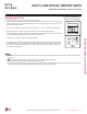

Indoor Unit Terminal Block
1(L) 2(N)
GND
3
Outdoor Unit Terminal Block or
Branch Distribution Unit Terminal Block
(Multi F MAX Systems Only)
GND
BR
BL
RD
3 or S
CN-REMO
To Wired Controller
YL
Comm.
(S)
RD
12V
Power
BK
Ground
Connections on
Wired Controller
DUCT (LOW STATIC) INDOOR UNITS
Installation and Best Layout Practices
Controller Options
Ceiling-concealed duct (low static) indoor units can be used with many LG-supplied wired controllers (sold separately). The wireless hand-
held controller (Model No. PQWRHQ0FDB) is also an optional accessory with use wired controllers.
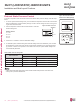
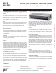
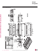
Figure 143:PZCWRC1 LG Wired Remote Extension Cable.
Verify the connectors are properly inserted.
C/BOX Cable (Plug type)
Extension cable
To Indoor Unit
CN-REMO
Terminal
TEMP
FAN
SPEED
OPER
MODE
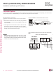
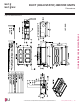
Figure 144:Wired Controller Connections on the Indoor Unit Terminal
Block.
When using eld-supplied controller cable, make sure to connect
the yellow to yellow (communications wire), red to red (12V power
wire), and black to black (ground wire) terminals from the remote
controller to the indoor unit terminal blocks.
Wired Controller Connections
Controllers can connect to the indoor unit in one of two different
ways.
1. LG Wired Remote Extension Cable with Molex plug (PZCWRC1;
sold separately) that connects to the CN-REMO terminal on the
indoor unit PCB.
2. Field-supplied controller cable that connects to the indoor unit
terminal block (must be at least UL2547 or UL1007, 22 AWG,
two-core, one-shield core, at least FT-6 rated if local electric and
building codes require plenum cable usage).
Due to our policy of continuous product innovation, some specications may change without notication.
©LG Electronics U.S.A., Inc., Englewood Cliffs, NJ. All rights reserved. “LG” is a registered trademark of LG Corp.
112 | DUCT (LOW STATIC)
Multi F and Multi F MAX Indoor Unit Engineering Manual
MULTI
F
MAX
MULTI
F